
12.07.2020
NASA Wraps Up Third SLS Core Stage Green Run Test, Eyes Test Fire This Fall
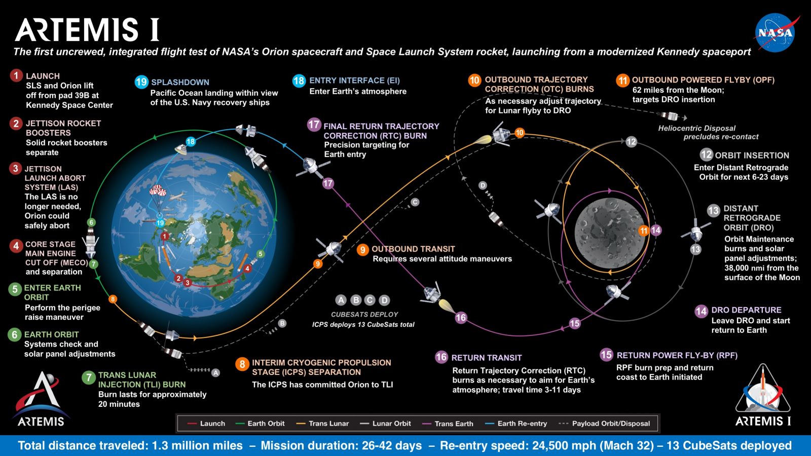
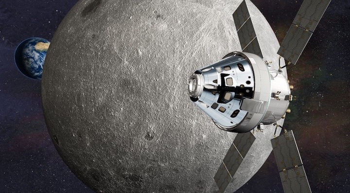
NASA engineers are approaching the midpoint of “Green Run” testing as the Space Launch System (SLS) core stage inches ever closer to a planned full-mission-duration static-firing of its four RS-25 engines, possibly later this fall. The space agency revealed Thursday that the third of eight critical Green Run tests has successfully concluded. The giant rocket, teamed with a pair of five-segment Solid Rocket Boosters (SRBs)—which arrived at the Kennedy Space Center (KSC) in Florida last month from prime contractor Northrop Grumman Corp.’s test site in Promontory, Utah—will send an uncrewed Orion spacecraft around the Moon late in 2021 for the Artemis-1 mission. In doing so, it will demonstrate the first human-rated space vehicle on a voyage to lunar distance since Apollo 17 in December 1972.
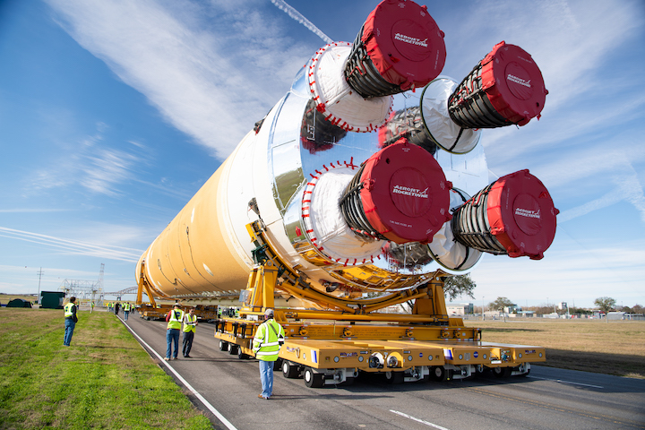
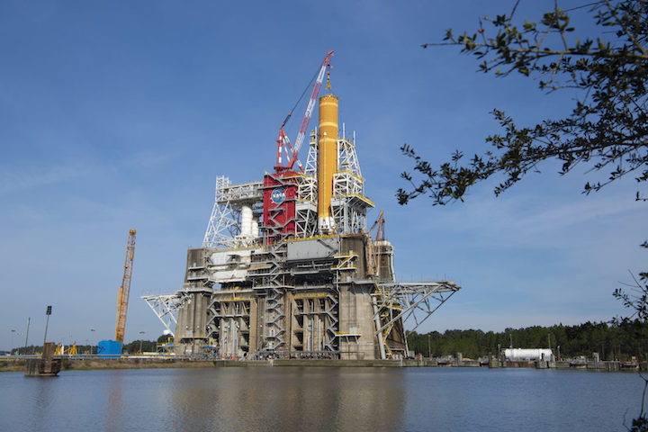
Green Run testing on the 212-foot-tall (64.6-meter) SLS core stage is being conducted in the B-2 Test Stand at NASA’s Stennis Space Center in Bay St. Louis, Miss. The core will be powered by four shuttle-era RS-25 engines, generating a combined impulse of about 1.6 million pounds (760,000 kg), which, when combined with the twin SRBs will give the SLS a total thrust at liftoff of 8.8 million pounds (3.4 million kg). This represents an approximately 15-percent increase over the long-since-retired Saturn V, which currently still stands as the largest and most powerful rocket ever brought to operational status.
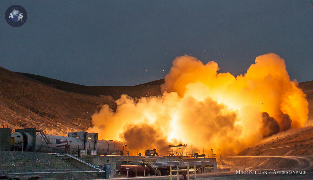
Testing of the SLS hardware has taken place on numerous fronts across the United States. The five-segment boosters—which derive in design from their shuttle-heritage predecessors—were put through an extensive series of evaluations, culminating in a pair of Qualification Motor (QM-1 and QM-2) firings at Northrop Grumman’s facility in Promontory, Utah, in March 2015 and June 2016, respectively, which tested their performance at “maximum” anticipated operating temperatures of 32 degrees Celsius (90 degrees Fahrenheit) and “minimum” anticipated operating temperatures of 4.5 degrees Celsius (40 degrees Fahrenheit).
More recently, five Structural Test Articles (STAs) of the critical components of the SLS core stage—its upper segment, intertank, liquid hydrogen tank, liquid oxygen tank and engine section—were put through 199 tests at NASA’s Marshall Space Flight Center (MSFC) in Huntsville, Ala. The upper section and intertank were tested first, followed by the engine section which wrapped up in February 2018.
More recently, last December the 149-foot-long (45.4-meter) liquid hydrogen tank, the biggest core stage element, was tested to destruction, and finally the 70-foot-long (21-meter) liquid oxygen tank was put through the wringer. In the case of the tanks, they endured far more punishing pressures and stresses than they can expect to receive on a real mission and provided not only valuable engineering data, but also a close-to-prediction endorsement of computer models.
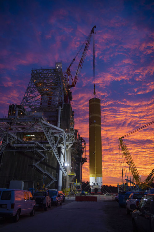
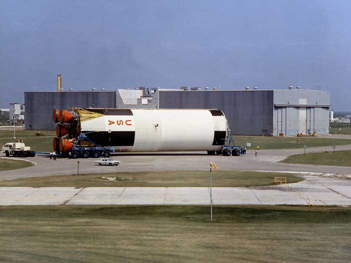
But the real test of the actual core stage for the SLS which will deliver Artemis-1 to the Moon took the form of the Green Run, conducted in the B-2 Test Stand at Stennis. Built in the 1960s, the stand is part of a dual-position, vertical static-firing complex upon which the S-IC first stage of the Saturn V and its quintet of F-1 engines were tested more than five decades ago and, more recently, housed the Main Propulsion Test Article framework to test the Space Shuttle’s main engines.

As part of preparing for the much larger and taller SLS, the stand saw extensive upgrades to to every major system and the addition of around a million extra pounds (453,500 kg) of steel to extend its framework an additional 100 feet (33 meters) and lengthen its large derrick crane. The new-look B-2 Test Stand was declared operationally “ready” in December 2018.
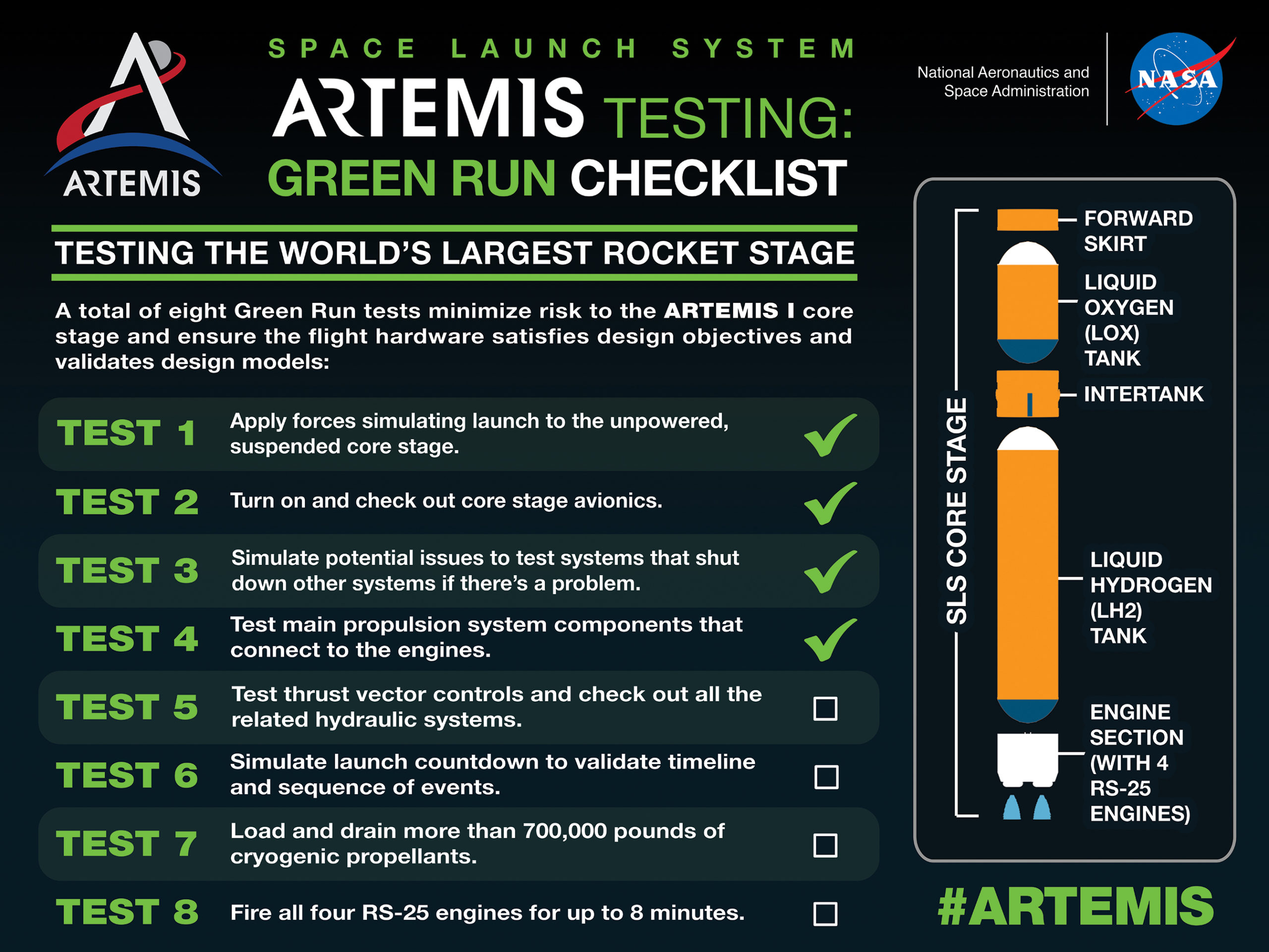
The Green Run is so named because its “run” of eight fully-integrated test phases will be conducted on new and as-yet-untried (or “green”) flight hardware. Last summer, NASA Administrator Jim Bridenstine stressed the importance of the Green Run in ensuring the safety of astronauts on future SLS flights, increasing the probability of achieving American boots on the Moon by 2024 and identifying technical issues “earlier rather than later”. In August 2019, a full-size structural replica of the SLS core stage, known as the “pathfinder”, was installed into the B-2 Test Stand for a series of fit-checks.

And earlier this year, the real SLS core stage for Artemis-1 made its way from NASA’s Michoud Assembly Facility in New Orleans, La., to Stennis. Delivered aboard the Pegasus barge, it arrived at the B-2 Test Stand dock in the second week of January and was lifted into the stand under optimal wind and weather conditions on the 21st and 22nd. Standing 212 feet (64.6 meters) tall, it is the largest core stage ever built by NASA, dwarfing even the 138-foot-tall (42-meter) S-IC first stage of the Saturn V.
“The SLS core stage is an engineering feat that includes not only the largest rocket propellant tanks ever built but also sophisticated avionics and main propulsion systems,” said Lisa Bates, SLS deputy stages manager. “While the rocket is designed to evolve over time for different mission objectives, the core stage design will remain basically the same. The Green Run acceptance test gives NASA the confidence needed to know the new core stage will perform again and again as it is intended.”
The first of the eight-test Green Run series was completed shortly afterwards, in the form of the “Modal Test”, which utilized mechanical “shakers” to impose dynamic forces on the suspended core stage to identify primary bending modes. Information from this test will aid the verification of vehicle models needed to operate the SLS Guidance, Navigation and Control (GNC) systems.
“Engineers also manually use an impulse hammer to test the spider crane, which holds the stage in place, to help establish a baseline for any impact the test stand or external hardware could have on Green Run testing data,” NASA noted. “Data from the modal test will be used to verify structural vibration modes and flight control parameters for the core stage design.”
The worldwide march of COVID-19 pushed Stennis into a “Level Four” posture on the scale of NASA’s response framework to the coronavirus pandemic in March, with only personnel needed to perform mission-essential activities relating to the safety and security of the center permitted on site.
Work resumed in a reduced capacity in mid-May and at the end of June the second Green Run test—the “Avionics Test”—was successfully completed. As part of this test, the rocket’s avionics, which are distributed throughout the core stage, were powered-up and checked out. This included the flight control computers and electronics and a multitude of sensors which gather flight data and montiro the overall health of the core stage in flight.
The third test, dubbed “Fail-Safes”, checked out the rocket’s safety systems which will shut down operations during testing and incorporated several simulations of potential problems. NASA confirmed the satisfactory completion of the Fail-Safes test in its Thursday update. Next up will be the “Propulsion” test, in which the core will be checked for leaks and command and control operations pertaining to the Main Propulsion System (MPS) elements adjoining the engines will be evaluated. The remaining tests, due to be conducted later this summer and into the fall, are expected to culminate and an up-to-eight-minute-long, full-mission-duration firing of the RS-25 engines.
“This critical test series will demonstrate the rocket’s core stage propulsion system is ready for launch on missions to deep space,” Stennis Director Rick Gilbrech said earlier this year. “The countdown to this nation’s next great era of space exploration is moving ahead.”
Quelle: AS
----
Update: 13.07.2020
.
NASA Assembles Artemis II Orion Stage Adapter
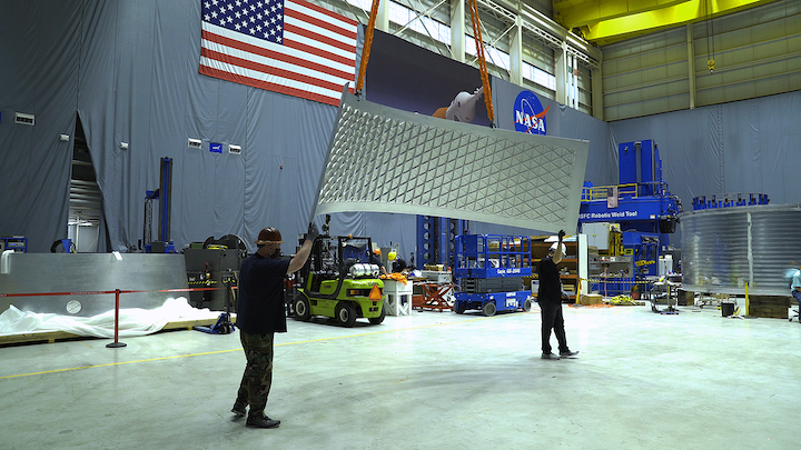
Technicians at NASA’s Marshall Space Flight Center in Huntsville, Alabama, have moved panels for the Artemis II Orion stage adapter to a large robotic, welding machine. Three panels were built by AMRO Fabricating Corp. in South El Monte, California and shipped to Marshall where engineers and technicians from NASA are joining them using a sophisticated friction-stir welding process to form the Orion stage adapter. This critical part of NASA’s Space Launch System (SLS) rocket will send the Artemis II crew into lunar orbit. AMRO also built panels for the Artemis II launch vehicle stage adapter also currently being built at Marshall and the SLS core stage and the Orion crew module built at NASA’s Michoud Assembly Facility in New Orleans. All panels where joined with the same friction-stir welding process. The Artemis I Orion stage adapter, also built at Marshall, has been delivered to Kennedy Space Center where it will be stacked with the rest of the SLS rocket components. The adapter connects the Interim Cryogenic Propulsion Stage (ICPS), the rocket’s upper stage that sends Orion to the Moon, to the Orion spacecraft. The Orion stage adaptor has space for small payloads; on Artemis I it will transport 13 small satellites to deep space where they can study everything from asteroids to the Moon and radiation. SLS, the world’s most powerful rocket, along with NASA’s Orion spacecraft, will launch America into a new era of exploration to destinations beyond Earth’s orbit.
NASA is working to land the first woman and the next man on the Moon by 2024. SLS, along with NASA’s Orion spacecraft, the Human Landing System and the Gateway in orbit around the Moon, are NASA’s backbone for deep space exploration. SLS is the only rocket that can send Orion, astronauts and supplies to the Moon on a single mission.
Quelle: NASA
----
Update: 18.07.2020
.
NASA’s inspector general criticizes Orion cost accounting
WASHINGTON — NASA’s inspector general criticized the agency for its accounting of Orion program costs in a new report, arguing it has “hindered the overall transparency” of the program amid growing costs and schedule slips.
In a July 16 report, NASA’s Office of Inspector General (OIG) raised several issues with costs of the Orion program, including the agency’s decision to exclude many costs from a formal cost estimate for the program as well as “overly generous” award fees paid to the prime contractor, Lockheed Martin, over the life of the program.
Through January of 2020, the latest financial data was available, NASA spent $16.7 billion on Orion, dating back to the Constellation program. NASA estimates spending $12.8 billion on Orion through 2030, primarily on production of future spacecraft.
While that suggests a total of Orion through 2030 of $29.5 billion, NASA’s formal estimate for life cycle costs for the program is $11.3 billion, covering development through the Artemis 2 mission. That total excludes the $6.3 billion spent on Orion during the now-defunct Constellation program and an estimated $10 billion in costs for missions beyond Artemis 2.
While life cycle cost estimates are supposed to cover the entire program, NASA granted approval for a tailored cost estimate, concluding, according to the report, that it would be difficult to estimate the overall cost “for a long-term human exploration program that is likely to last for multiple decades.” However, OIG said that approach limited the ability of those outside the agency to track development “and determine whether a replan or rebaseline of program funding and schedule expectations is required.”
“Furthermore, without a complete and comprehensive picture of Orion’s Life Cycle Cost, it is difficult for Congress and other stakeholders to have the information necessary to inform strategic decisions regarding future human exploration priorities,” the OIG report added.
Even with the limited scope of life cycle costs, there are signs of overruns. While NASA used the $11.3 billion as its formal “agency baseline commitment” for Orion, costs are now estimated to be $12.2 billion, of which $7.7 billion is for development. Those development costs have grown by nearly 14%, nearing the 15% threshold that requires formal congressional notification. OIG said additional cost growth of about $500 million is currently projected through 2023.
The report said that “performance shortcomings” by Lockheed Martin contributed to those cost overruns and some schedule slips, although those delays have been masked to some degree by greater schedule problems with the Space Launch System. OIG, citing internal NASA documents, said the Artemis 1 mission is now scheduled for launch in November 2021 and Artemis 2 in August 2023, although agency leadership has yet to confirm those dates.
Despite those challenges, the OIG report found that Lockheed still received $740.9 million in award fees dating back to 2006, or 90.2% of the total amount the company was eligible to earn. Part of that is that final scores given to the company during evaluations of its performance “were consistently higher than the composite of the individual factor scores” used in that evaluation.
NASA officials say that officials can increase those scores by considering higher-level issues beyond the scope of the company. However, OIG concluded that “deeming its work consistently ‘Excellent’ appears overly generous given the program’s longstanding cost and schedule growth.”
OIG made three recommendations to NASA: including all costs for Orion in future reports, adjusting production schedules for later Orion spacecraft and minimizing award fees if future contracts have to be modified because of contractor performance.
The agency, in a response included in the report, said it would implement all three recommendations. However, OIG noted that NASA didn’t commit to including Constellation-era Orion costs in those future reports. Doing so might not be practicable, OIG acknowledged, but “in our judgment a complete picture of Orion’s Life Cycle Costs should include all costs related to a program regardless of funding source or management control over its planned lifespan.”
Quelle: SN
----
Update: 30.07.2020
.
First SLS LVSA ready for Artemis 1, second in production
The interstage connector for the first NASA Space Launch System (SLS) vehicle was delivered to NASA in mid-July and is in transit to its launch site. The Launch Vehicle Stage Adapter (LVSA) was completed by Teledyne Brown Engineering at the Marshall Space Flight Center (MSFC) in Alabama and officially turned over to the agency for use on the Artemis 1 launch, tentatively scheduled for late 2021.
While the first flight LVSA unit was placed on NASA’s Pegasus barge and towed through U.S. waterways to the Kennedy Space Center (KSC) in Florida, work to weld the second LVSA structure is well underway at MSFC. Plans are to have the second unit ready for the Artemis 2 vehicle by mid-2022 and NASA has also placed orders for the long-lead raw materials necessary to build fabrication of a third LVSA.
First flight unit headed to KSC on Pegasus
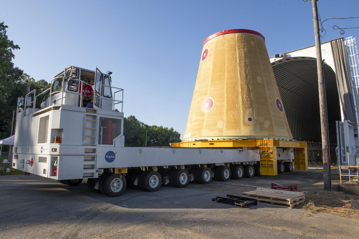
Early on July 17, the LVSA was rolled out of its final integration site, Building 4649 at Marshall, to the agency’s Pegasus barge for the trip to the launch site. Tugboats moved the barge out to the Mississippi River and south to the New Orleans area, where the barge stopped at the Michoud Assembly Facility (MAF).
“The LVSA departed Marshall back on the 17th which was last Friday and so as of today [it] is on the Pegasus barge being transported down to KSC,” Keith Higginbotham, NASA LVSA manager for the SLS Program, said on July 23. “It arrived at MAF just today and they offloaded another element’s hardware.”
“They offload that today and they also put the spider assembly on the Pegasus as well and so that’ll be getting transported along with the LVSA down to the Cape. We’re scheduled to get to the Cape barring any weather delays probably about the second of August.”
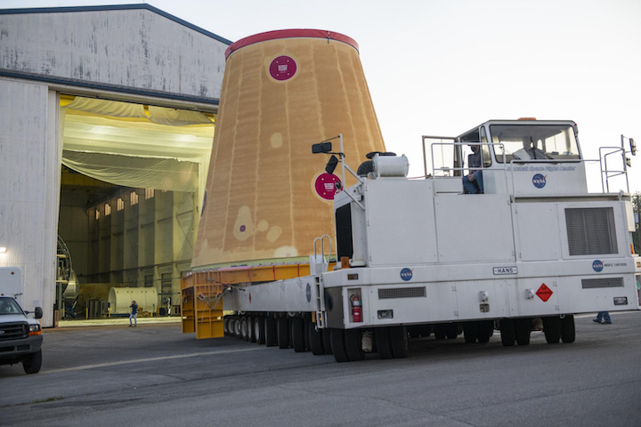
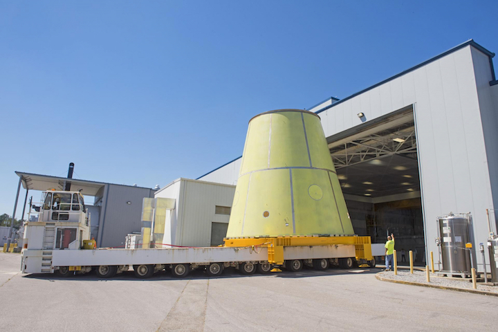
(Photo Caption: A transporter rolls the LVSA out of Building 4649 at MSFC on July 17. The adapter was transported to the Pegasus barge for shipment to its Kennedy Space Center launch site.)
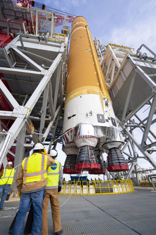
The lift spider is a twenty-plus ton fixture that is attached to the forward end of Core Stages to help lift and rotate them from horizontal to vertical orientation and vice versa. It will be used at KSC to help mate the first Core Stage to the SLS solid rocket boosters (SRB) next year.
The other lift spider is currently attached to that first Core Stage as it goes through its Green Run test campaign at the Stennis Space Center in Mississippi. In addition to the lift spider, two of the self-propelled modular transporters (SPMT) used to move Core Stages outdoors on their horizontal transporter were also loaded on the barge at MAF, with the spider mounted on one of them. The SPMTs will eventually head back with Pegasus to Mississippi to pick up the Core Stage at the conclusion of the Green Run campaign for delivery to KSC.
After the exchange of secondary equipment at MAF, the barge was picked up by oceangoing tugboats and departed on July 24. From New Orleans, the route to the launch site goes through the Gulf of Mexico, south and around the Florida Peninsula, and then north up the east coast to Port Canaveral and eventually the Turn Basin at KSC.
On arrival, NASA’s Exploration Ground Systems (EGS) program at KSC will receive the LVSA for eventual integration of the first SLS vehicle for launch on Artemis 1. The element will be stored in the Vehicle Assembly Building (VAB) until those activities start, likely next year.
The timing of launch vehicle integration (also called “stacking”) on Mobile Launcher-1 (ML-1) depends on when the Core Stage arrives at KSC. The SLS core will be the last major hardware element to arrive at the launch site for Artemis 1 and its delivery is dependent on completion of the ongoing Green Run testing.
For now, the LVSA will be parked in High Bay 4 of the VAB, which is a staging area for most SLS hardware prior to lifting into the High Bay 3 integration cell where ML-1 is set up. In the meantime, some practice exercises will be conducted while the LVSA is in storage.
“We have some additional ground support equipment like internal access platforms and a test stand,” Allison Mjoen, NASA EGS Operations Project Engineer, said. “We want to be able to run through getting our operational experience with the technicians and the engineers to use those platforms and there are some human factors assessments that’ll be associated with that as well.”
“Those are the platforms that we will be installing inside the LVSA once we’re stacked,” she noted. “So we’ll be doing preps like that as well to make sure our team is in good working order once we go into our integrated operation.”
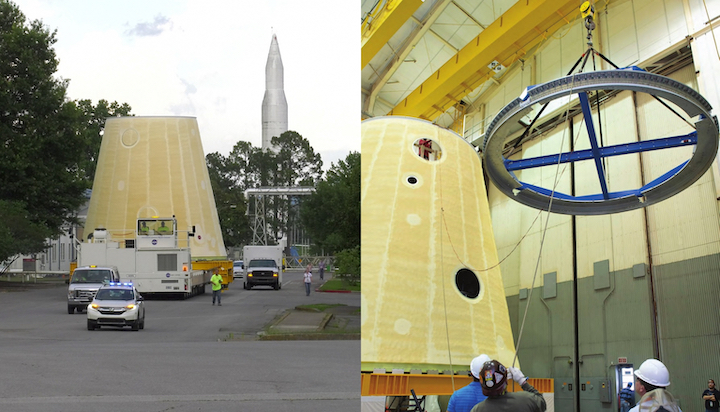
(Photo Caption: On the left, the LVSA was moved to Building 4649 at MSFC for final integration work in June, 2018. On the right later in 2018, a frangible joint assembly is lifted to be attached to the top of the adapter; the assembly will separate the ICPS upper stage from the LVSA during launch.)
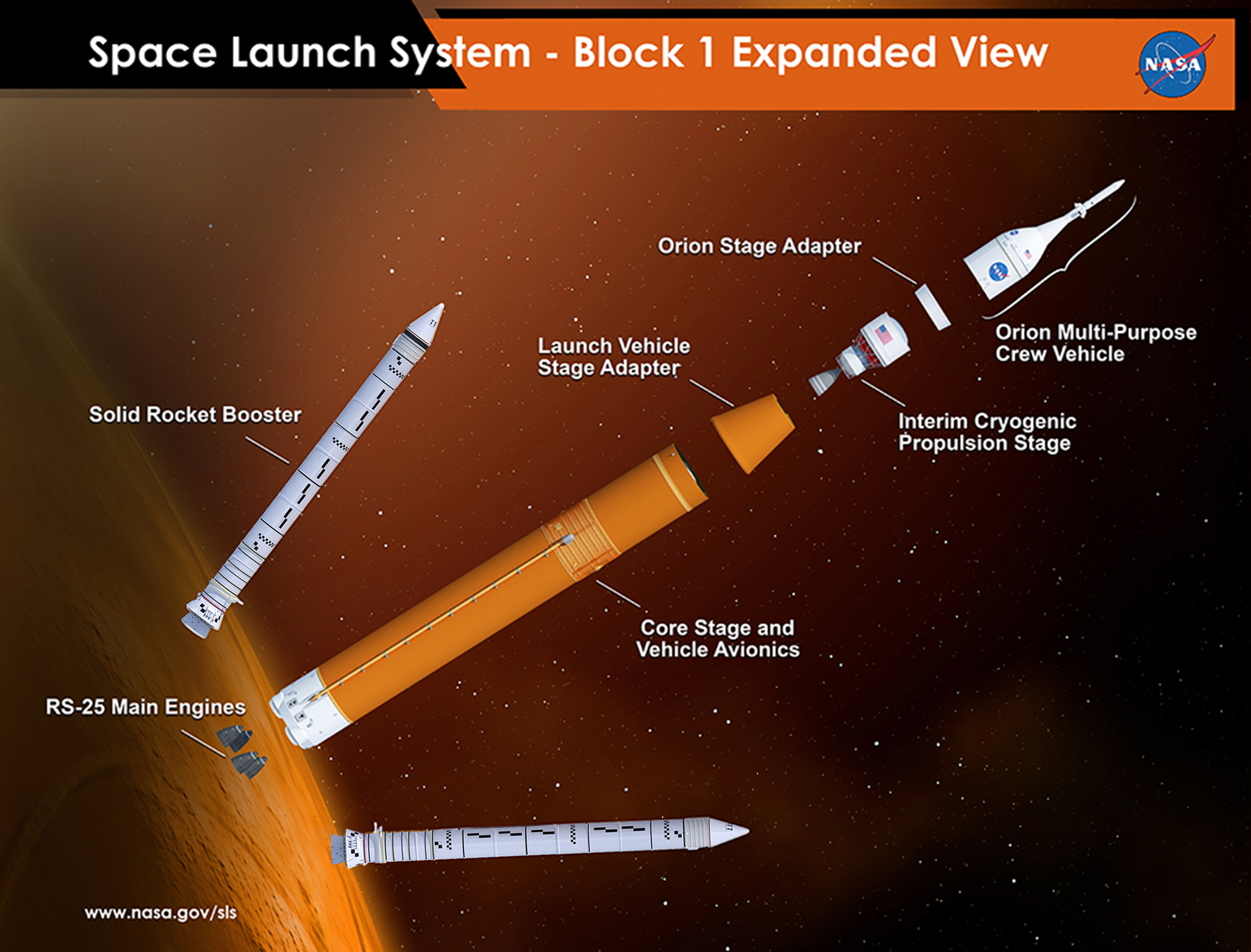
The LVSA is part of the Integrated Spacecraft and Payload Element (ISPE) of the SLS Block 1 vehicle; in both Crew and Cargo configurations, it connects the Core Stage with the Block 1 upper stage, the Interim Cryogenic Propulsion Stage (ICPS).
The adapter is primarily a structural interstage connector, with the bottom bolted to the forward skirt of the Core Stage and the top attached to the hydrogen tank of the ICPS. Most of the upper stage including its single RL-10B-2 engine and stowed nozzle extension is enclosed by the LVSA during launch and ascent.
Following Core Stage main engine cut off (MECO), the LVSA stays with the Core and the ICPS separates from the top of the adapter. The adapter includes a separation system and a frangible joint assembly that is sandwiched by the ICPS and LVSA.
The frangible joint assembly instantaneously separates the upper stage from the LVSA at the appropriate time without generating any debris from the explosive detonation.
The outside of the adapter is covered with spray-on foam insulation (SOFI). In the case of the LVSA, the foam thermally protects the adapter and its contents from heating during ascent through the lower atmosphere.
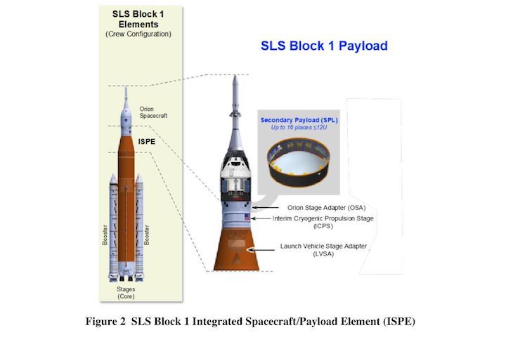
(Photo Caption: A NASA diagram showing the three parts of the SLS Block 1 Crew configuration’s Integrated Spacecraft Payload Element; adapters sandwich the ICPS upper stage, with the LVSA connecting the Core Stage below and the Orion Stage Adapter (OSA) connecting the Orion spacecraft above.)
Although the adapter is mostly structure, it also includes electrical harnesses to connect the Core Stage flight control system below with the LVSA separation system, upper stage flight computers and the Orion spacecraft and crew above. The vehicle is also covered with development flight instrumentation (DFI) for its first launch and all those sensors are connected to the Core Stage’s data acquisition system.
“ICPS will fit down in the volume of the LVSA, so you have some DFI that’s connected through our adapter that runs from top to bottom, so there’s some of that,” Higginbotham noted. “The other thing that I would mention is that we’ll have a couple of camera assemblies inside so that once the separation event occurs, the ICPS will go about its way and upon its departure from inside the LVSA there will be cameras that will capture that event as it occurs.”
The two cameras in the stage adapter are among several mounted around the launch vehicle that are wired into the Camera Control Unit (CCU) in the Core Stage’s intertank that will collect data from them during launch and ascent. From a few seconds prior to MECO to several seconds after, views from the LVSA cameras capturing ICPS separation will be relayed via telemetry to ground receiving stations.
There are also multiple circular access doors around the circumference of the adapter, which will be used during stacking operations at KSC. “Once we get ready to do the stacking [they] will allow us to go through those access doors with platforms [when] we actually do the mating,” Higginbotham said.
Teledyne Brown Engineering hands first LVSA keys over to NASA
The Artemis 1 LVSA is the first flight unit produced by prime contractor Teledyne Brown Engineering but the second structure fabricated for the program. The first unit was the basic welded structure used in a structural test article of the ISPE elements.
“The first one that we built for the structural test article (STA) was basically more of a monocoque structure that didn’t have all the orthogrid patterns and stuff that we did [for the flight unit],” Higginbotham noted. “We took it up to limit and ultimate load so we qualified that the hardware will be able to fly with the requirements that you would have when you have people on board.”
Limit load is 100 percent of the estimated maximum flight loads. Ultimate load is 140 percent of the maximum flight loads that the vehicle structure is required to support in order to meet the 1.4 factor of safety requirement for human-rating.
(Photo Caption: The welded LVSA structure for the first SLS launch is moved into Building 4707 at MSFC in August, 2017, for application of its spray-on foam outer covering.)
The first flight unit was welded in the same location, the Advanced Weld Facility in Building 4755 at Marshall. The structure is a tapered cone composed of sixteen panels and a ring at the top and bottom. The panels were manufactured by AMRO Fabricating Corporation in California before delivery to Teledyne Brown based in Huntsville, Alabama, area near Marshall.
“All the plates were machined and fabricated out there [at AMRO],” Higginbotham said. “They go through a proprietary bump-forming process that they use to make the panels for this kind of structure.”
“They shipped the panels to Teledyne where it goes through inserts and installations and then gets transferred out to Marshall.”
Following welding, the completed structure was transferred to Building 4707 at Marshall in August, 2017, for thermal protection system (TPS) application. The flight units are treated with primer for corrosion protection on the exterior before being sprayed with SOFI.
The LVSA was moved to Building 4649 at Marshall in June, 2018, for final integration activities in the high bay there.
“It was over in Building 4707 where the TPS was applied and finished, then it got transported over to Building 4649 where we did most of the final integration work,” Higginbotham noted. “So that was where the FJA, the frangible joint assembly, got installed and then it was about three or four months to outfit the rest of it with the pneumatic actuation system, which is lined all within the inner walls of the LVSA.”
“We had that, we had the remainder of the DFI sensor cabling that we had to install, we had the camera assemblies, and then the other major thing that I would mention is the acoustic blankets that we had to put on the inside, that was one of the final things that were installed inside.”
Higginbotham also noted that a hazardous gas vent assembly and Environmental Control System (ECS) vent assembly were also installed during final integration. As launch vehicle stacking is finally drawing near, the element was officially transferred from Teledyne Brown to NASA at Marshall for launch processing some time after delivery to KSC.
“We took the ownership when it vacates 4649 and it starts its trip down to the Cape, that’s when NASA takes over the hardware,” Higginbotham said.
Quelle: NS
----
Update: 9.08.2020
.
NASA Hits Green Run Midpoint, Eyes End-of-Year SLS Static Fire
NASA engineers have reached the midpoint of “Green Run” testing as the first Space Launch System (SLS) core inches ever closer to a planned full-mission-duration static-firing of its four RS-25 engines, possibly later this fall. The space agency revealed Thursday that the fourth of eight critical Green Run tests successfully concluded on Wednesday, 5 August. The giant rocket, teamed with a pair of five-segment Solid Rocket Boosters (SRBs)—which arrived at the Kennedy Space Center (KSC) in Florida in June from prime contractor Northrop Grumman Corp.’s test site in Promontory, Utah—will send an uncrewed Orion spacecraft around the Moon late in 2021 for the long-awaited Artemis-1 mission. In doing so, it will demonstrate the first human-rated space vehicle on a voyage to lunar distance since Apollo 17 in December 1972.
“Progress!” tweeted NASA Administrator Jim Bridenstine on Thursday. “The fourth test of the @NASA_SLS core stage Green Run test series is complete. Teams finished testing the main propulsion system components within the core stage that connect the rocket’s four RS-25 engines.” Core stage prime contractor Boeing added that this latest test had successfully “verified command-and-control and checked for leaks”.
Green Run testing on the 212-foot-tall (64.6-meter) SLS core stage is being conducted in the B-2 Test Stand at NASA’s Stennis Space Center in Bay St. Louis, Miss. The core will be powered by four shuttle-era RS-25 engines, generating a combined impulse in excess of 1.6 million pounds (760,000 kg), which, when combined with the twin SRBs will give the SLS a total thrust at liftoff of 8.8 million pounds (3.4 million kg). This represents an approximately 15-percent increase over the long-since-retired Saturn V, which currently still stands as the largest and most powerful rocket ever brought to operational status.
Testing of SLS hardware has taken place on numerous fronts across the United States. The five-segment boosters—which derive in design from their shuttle-heritage predecessors—were put through extensive evaluations, culminating in a pair of Qualification Motor (QM-1 and QM-2) firings at Northrop Grumman’s facility in Promontory, Utah, in March 2015 and June 2016, which tested their performance at “maximum” anticipated operating temperatures of 32 degrees Celsius (90 degrees Fahrenheit) and “minimum” anticipated operating temperatures of 4.5 degrees Celsius (40 degrees Fahrenheit).
More recently, five Structural Test Articles (STAs) of the critical components of the SLS core stage—its upper segment, intertank, liquid hydrogen tank, liquid oxygen tank and engine section—were put through 199 tests at NASA’s Marshall Space Flight Center (MSFC) in Huntsville, Ala. The upper section and intertank were tested first, followed by the engine section which wrapped up in February 2018.
More recently, last December the 149-foot-long (45.4-meter) liquid hydrogen tank, the biggest core stage element, was tested to destruction, and finally the 70-foot-long (21-meter) liquid oxygen tank was itself put through the wringer. In the case of both tanks, they endured far more punishing pressures and stresses than they can ever expect to receive on a real mission and provided not only valuable engineering data, but also a close-to-prediction endorsement of computer models.
But the real test of the core stage for the actual SLS which will power Artemis-1 to the Moon took the form of the Green Run, conducted in the B-2 Test Stand at Stennis. Built in the 1960s, the stand is part of a dual-position, vertical static-firing complex upon which the S-IC first stage of the Saturn V and its quintet of F-1 engines were tested more than five decades ago and, more recently, housed the Main Propulsion Test Article framework to test the Space Shuttle’s main engines.
As part of preparing for the much larger and taller SLS, the stand saw extensive upgrades and the addition of around a million extra pounds (453,500 kg) of steel to extend its framework an additional 100 feet (33 meters) and lengthen its large derrick crane. The new-look B-2 Test Stand was declared operationally “ready” in December 2018.
The Green Run is so named because its “run” of eight fully-integrated test phases will be conducted on new and as-yet-untried (or “green”) flight hardware. Last summer, Mr. Bridenstine stressed the importance of the Green Run in ensuring the safety of astronauts on future SLS flights, increasing the probability of achieving American boots on the Moon by 2024 and identifying technical issues “earlier rather than later”. In August 2019, a full-size structural replica of the SLS core stage, known as the “pathfinder”, was installed into the B-2 Test Stand for a series of fit-checks.
Quelle: AS
----
Update: 16.08.2020
.
Penultimate piece of NASA’s first SLS rocket arrives at Kennedy Space Center
One of the final pieces for the first test flight of NASA’s huge Space Launch System heavy-lift rocket recently arrived at the Kennedy Space Center, joining other elements already at the Florida spaceport awaiting shipment of the SLS core stage once it completes testing at a NASA facility in Mississippi.
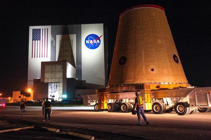
The Launch Vehicle Stage Adapter, or LVSA for the first SLS test launch arrived at the Kennedy Space Center in Florida aboard NASA’s Pegasus barge July 29. Early the next day, hours before the liftoff of NASA’s Mars 2020 Perseverance rover from a launch pad a few miles away, ground crews transferred the LVSA from the Pegasus barge into the Vehicle Assembly Building at the Florida spaceport.
The LVSA is the second-to-last element of the first Space Launch System rocket to arrive at the Kennedy Space Center. The biggest piece of the rocket, known as the core stage, is expected to arrive at Kennedy after test-firing of its four