
21.07.2019
NASA’s Orion crew capsule is officially complete and ready to prep for its first Moon mission
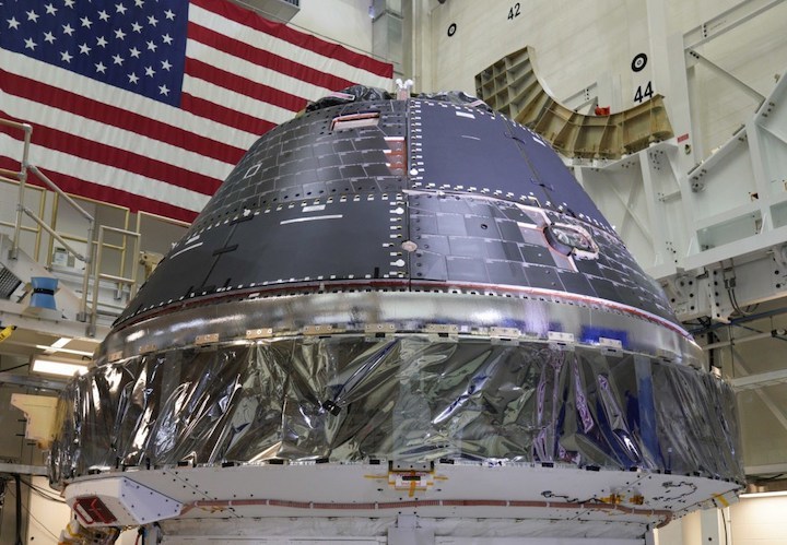
NASA’s 50th anniversary celebrations weren’t limited to just remembrances of past achievements – the space agency also marked the day by confirming that the Orion crew capsule that will bring astronauts back to the Moon for the first time since the end of the Apollo program is ready for its first trip to lunar orbit, currently set for sometime after June 2020.
Orion won’t be carrying anyone for its first Moon mission – instead, as part of Artemis 1, it’ll fly uncrewed propelled by the new Space Launch System, spend a total of three weeks in space including six days orbiting the Moon, and then return back to Earth. Once back, it’ll perform a crucial test of high speed re-entry into Earth’s atmosphere, to demonstrate the efficacy of the Orion capsule’s thermal shielding prior to carrying actual crew for Artemis 2 in 2022, and ultimately delivering astronauts back to the lunar surface with Artemis 3 in 2024.
This isn’t Orion’s first trip to space, however – that happened back in 2014 with Exploration Flight Test 1, another uncrewed mission in which Orion spent just four-hours in space, orbiting the Earth twice and then returning to ground. This mission used a Delta IV rocket instead of the new SLS, and was meant to test key systems prior to Artemis.
On the anniversary of the Apollo Moon landing, the Lockheed Martin-built Orion capsule for the Artemis 1 mission to the Moon is declared finished.
NASA contractor Lockheed Martin, which is responsible for the Orion spacecraft’s construction, also noting that the combined crew module and service module are currently being properly integrated, and then will undergo a series of tests before returning to Kennedy Space Center in Florida by the end of the year to begin the final preparations before launch.
Quelle: TC
----
Update: 9.08.2019
.
NASA Administrator to Discuss Status of Rocket for First Artemis Lunar Mission
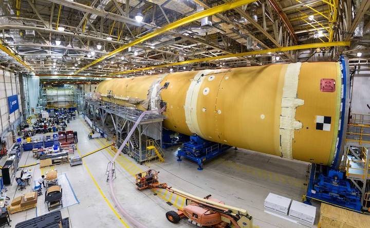
Media are invited to accompany NASA Administrator Jim Bridenstine Thursday, Aug. 15, on his visit to the agency’s Michoud Assembly Facility in New Orleans, where engineers are preparing to add the final section to the core stage of the rocket that will power NASA’s Artemis 1 lunar mission.
Bridenstine will meet with members of the Space Launch System (SLS) program to discuss and view progress on the rocket and take questions from media at 11:30 a.m. CDT in front of SLS’s 212-foot-tall core stage.
U.S. media who would like to attend the event should contact Tracy McMahan at 256-544-0034 or tracy.mcmahan@nasa.gov no later than 5 p.m. Tuesday, Aug. 13, and plan to arrive at Michoud by 10:30 a.m. Aug. 15, with at least one form of government-issued photo identification. Long pants and flat, closed-toe shoes are required.
Assembly of the core stage, the largest and most complex stage NASA ever has built, remains on schedule for completion before the end of the year. Comprised of two liquid propellant tanks and four RS-25 engines, it will produce more than two million pounds of thrust to send NASA’s Orion spacecraft, crew and cargo to the Moon.
NASA is working to land the first woman and the next man on the Moon by 2024. SLS is the only rocket that can send Orion, astronauts and supplies to the Moon on a single mission. The rocket, Orion spacecraft and Gateway in orbit around the Moon, are NASA’s backbone for deep space exploration.
Quelle: NASA
----
Update: 11.08.2019
.
Hot Fire! Orion’s Service Module Completes Critical Propulsion Test
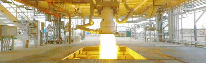
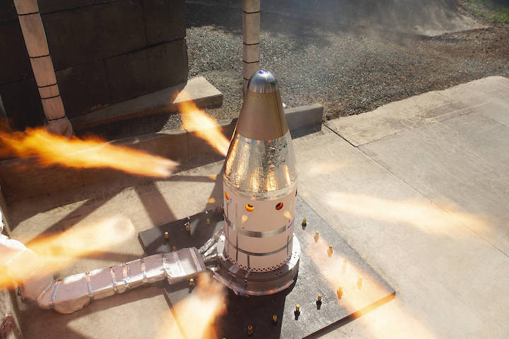
NASA is building a system to send astronauts to the Moon for Artemis missions, and that includes tests to make sure the Orion spacecraft is prepared to safely carry crew on an alternate mission profile in the face of unexpected problems. That capability was most recently demonstrated with a successful, continuous 12-minute firing of Orion'spropulsion system that simulated a possible alternate mission scenario.
“Inserting Orion into lunar orbit and returning the crew on a trajectory back home to Earth requires extreme precision in both plotting the course and firing the engines to execute that plan,” said Mark Kirasich, program manager for Orion at NASA’s Johnson Space Center in Houston. “With each testing campaign we conduct like this one, we’re getting closer to accomplishing our missions to the Moon and beyond.”
The Aug. 5 test was conducted using a qualification version of the propulsion system at NASA’s White Sands Test Facility near Las Cruces, New Mexico. While the system never left the ground, it simulated one of the most taxing situations the spacecraft’s engines could encounter after launch.
This test simulated what is referred to as an abort-to-orbit scenario. In the event the interim cryogenic propulsion stage (ICPS) was unable to set the spacecraft on its path to the Moon, Orion would deliberately separate early from the ICPS and the ESA (European Space Agency)-provided service module’s engines would fire to boost the spacecraft into a safe, temporary orbit. That would allow time to evaluate the crew and spacecraft before a decision is made to either continue with an alternate mission profile, or return to Earth. Under an alternate mission profile, Orion and its crew may still be able to accomplish some of the mission objectives even if the trajectory and the primary mission objective has changed.
During the successful test, engineers simulated the abort-to-orbit scenario by firing the Orion main engine on the service module, in addition to all eight of its auxiliary engines simultaneously. Each of the reaction control thrusters were also periodically fired throughout the test to simulate attitude control and overall propulsion system capacity.
“This was our most demanding test for the pressurization system, including our propellant tanks, valves and other components,” said Josh Freeh, deputy manager, Orion’s Service Module, at NASA’s Glenn Research Center. “The combined international team has been working towards this test for many months.”
The qualification version of the service module’s propulsion system serves as a testbed to verify the performance of the multiple types of engines, propellant systems and other propulsion-related subsystems.
“The tests at White Sands have been very helpful to better understand and operate our service module propulsion system,” said Jim Withrow, project manager for the test article. “This firing was one of a series of tests performed to date and in the coming months to simulate contingency modes and other stressful flight conditions.”
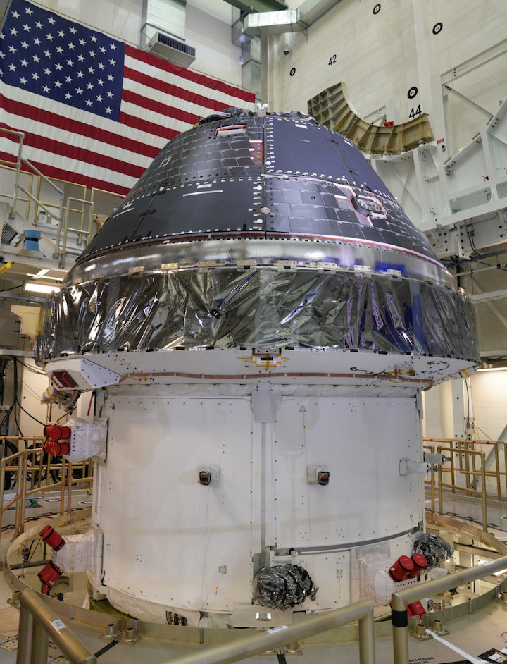
As the powerhouse of the Orion spacecraft, the service module provides in-space maneuvering, power and other astronaut life support systems, including consumables like water, oxygen and nitrogen. Engineers at NASA’s Kennedy Space Center are joining the completed Artemis 1 crew module and service module together, before sending the spacecraft to NASA’s Plum Brook Station in Sandusky, Ohio, later this fall for simulated in-space environmental testing. Once testing is complete in Ohio, the spacecraft will return to Kennedy for final processing and integration with the Space Launch System (SLS) rocket.
Artemis 1 will be the first, full test flight of the SLS and Orion as it is sent around the Moon. The uncrewed test will precede Artemis 2, the first flight with astronauts aboard, and both will pave the way for the first woman and the next man to land on the Moon by 2024, while preparing for future missions to Mars.
Quelle: NASA
----
Update: 20.08.2019
.
SLS contractors expect first launch in 2021

WASHINGTON — While NASA has yet to update the schedule for the first flight of its Space Launch System, companies working on the heavy-lift rocket now expect the rocket to launch in early 2021 rather than 2020.
The first launch of the SLS, on a mission called Artemis 1, had been formally scheduled for the second half of 2020, a date that already represented two years’ worth of delays. That date is under review as NASA brings in new leadership for its exploration programs after reassigning former associate administrator Bill Gerstenmaier and his deputy, Bill Hill, in July.
During an Aug. 19 panel discussion at the American Institute of Aeronautics and Astronautics’ Propulsion and Energy Forum in Indianapolis, executives with companies involved with the SLS projected that, based on what work needs to be done to complete the vehicle for launch, that launch probably won’t take place before early 2021.
Jeff Foote, vice president of NASA programs at Northrop Grumman Innovation Systems, said he expected that, with the agency deciding to perform a “Green Run” static-fire test of the core stage at the Stennis Space Center next year, that core stage won’t arrive at the Kennedy Space Center for launch preparations until late 2020.
“From that time forward, with the integration of Orion, wet dress rehearsal and that sort of thing, there’s probably two quarters, maybe two and a half quarters, or work to get to a launch date,” he estimated. “So, most likely early in 2021. It could happen earlier, it could happen later.”
The core stage has been on the critical path for the launch for some time because of problems with its engine section. Both NASA and Boeing now expect the core stage to be completed and ready to ship to Stennis at the end of the year.
“We’ll probably fire it off in the second or third quarter of next year, and do a full test,” Robert Broeren, the integrated product team lead for SLS stages at Boeing, said of the Green Run test on the panel. “After that, it probably takes quite a bit of time to do rework and some upgrades to it, then we’ll put it on a barge and send it down to the Cape.”
Earlier this year NASA said it was considering whether the Green Run test was necessary, since skipping it could save several months of schedule. However, NASA Administrator Jim Bridenstine announced July 25 that NASA would go ahead with the test.
Bridenstine visited the Michoud Assembly Facility in New Orleans where Boeing is building the core stage Aug. 15, and said later he was impressed with the progress that we saw. “What I saw there was absolutely eye-watering,” he said Aug. 16 during a separate event at the Marshall Space Flight Center. He acknowledged the challenges in the engine section that delayed completion of the core stage, and NASA’s efforts to get around it by integrating the other sections of the core stage first.
That engine section, he said, is nearly ready to be integrated to the rest of the core stage, to be followed by its four RS-25 engines. He confirmed that work should be completed by the end of the year.
Bridenstine didn’t discuss the schedule for Artemis 1 in those remarks, but in July 17 testimony before the Senate Commerce Committee suggested a first launch in 2021, rather than 2020, was likely. “I think 2021 is definitely achievable” for that mission, he said then, but noted he wanted to bring in new leadership for the agency’s exploration program before setting a firm date.
A slip to 2021 would not necessarily delay the first crewed SLS/Orion mission, Artemis 2, now scheduled for 2022. “If Artemis 1 launches no later than mid 2021, there will be no impact to Artemis 2,” Bridenstine said in an Aug. 3 email to Sen. Mike Enzi (R-Wyo.), who several days earlier wrote to the NASA administrator about his concerns about cost and schedule problems with SLS and other major NASA programs.
“This is a realistic plan,” Bridenstine added, “but I would like to have new leadership in place and committed to an integrated schedule before committing to a date.”
Quelle: SN
----
Update: 25.08.2019
.
Orion Hot Fire Test Blazing a Safe Trail for NASA Missions to the Moon
The Northrop Grumman built attitude control motor (ACM) on Orion's launch abort system was successfully tested on August 22, at their facility in Elkton, Maryland.
The 30-second trial by fire was the second to last test before it’s qualified for human spaceflight on Artemis 2 -- the first mission with astronauts. During the static test, the ACM produced more than 7,000 pounds of thrust from eight valves, providing enough force to steer Orion and its crew to a safe distance.
The launch abort system is designed to transport Orion and its crew to safety in the event of an emergency during launch or ascent. It consists of three solid rocket motors: the abort motor pulls the crew module away from the launch vehicle; the ACM steers and orients the capsule; then the jettison motor ignites to separate the launch abort system from Orion for parachute deployment and a safe crew landing.
All three motors will be certified for future crewed flights after qualification tests are completed later this year. The launch abort system was stress tested earlier this year during the successful Ascent Abort-2 test.
These achievements brings Orion closer to safe flights with astronauts, paving the way for the first woman and the next man to land on the Moon by 2024.
NASA’s Orion Heat Shield: Old Materials, Applied With New Methods
Gone is the caulk gun-like technique dating back to Apollo.
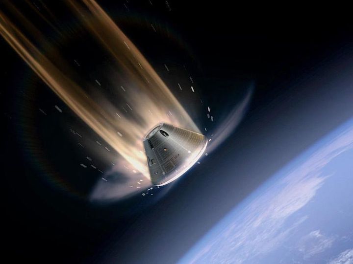
The capsule that carried Apollo 11 astronauts safely back to Earth in 1969 used a heat shield made of epoxy resin to protect its contents from the 5,000-degree heat of reentry. The resin, called Avcoat, was designed to erode, carrying heat away from the surface. A half century later, NASA’s Orion spacecraft uses the same material. Brian Hinde, Lockheed Martin’s Orion Structures and Aeroshell Senior Manager, says that the most important innovation for heat shield technology isn’t finding new materials, but increasing the efficiency of materials already in use. On the Apollo capsule, the Avcoat was injected into thousands of individual cells of a fiberglass honeycomb, an agonizingly slow process. The tool used was, in essence, “a high-pressure caulk gun,” says Hinde.
For Orion, the caulk gun at least is gone. Now the resin is produced in billets. “Then we very efficiently model and 3D machine very accurately—by keeping everything in the computer—the exact shape of the tiles we want and bond them on,” he says. The new process saves time and weight. Matt Gasch of NASA Ames Research Center puts into perspective the reliance on trusted materials. Heat shields are a “single point of failure,” he says. “They either work or they don’t.”
Quelle: Air&Space
----
Update: 10.09.2019
.
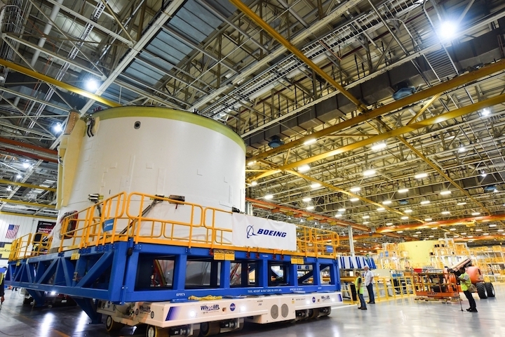
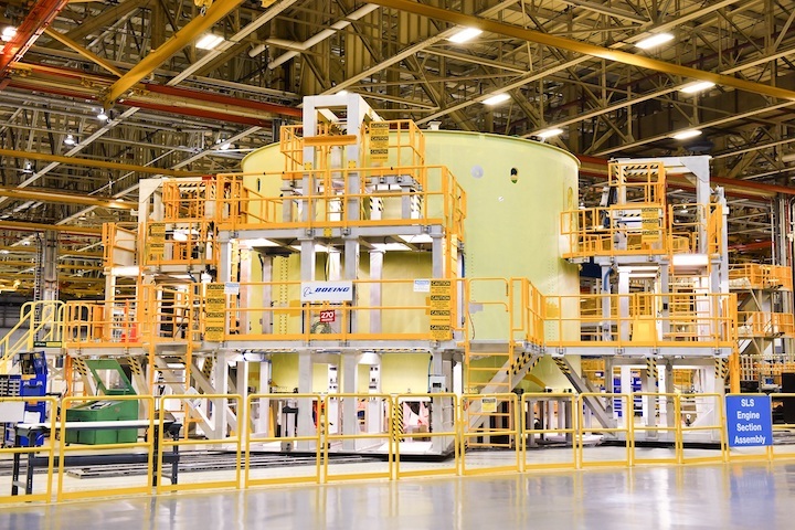
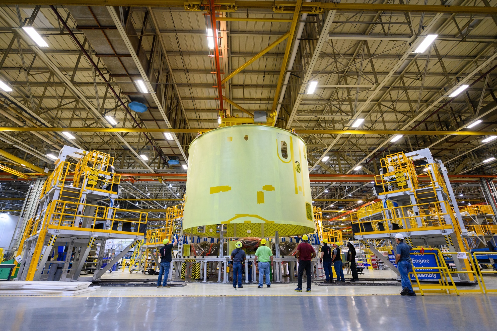
Engine Section for NASA's SLS Rocket Moved for Final Integration
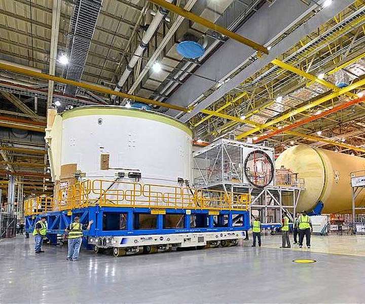
Technicians at NASA's Michoud Assembly Facility in New Orleans moved the engine section for NASA's Space Launch System (SLS) rocket to another part of the facility on Sept. 3 to prepare it for joining to the rest of the rocket's core stage.
The engine section, which comprises the lowest portion of the 212-foot-tall stage, is the last major component to be horizontally integrated to the core stage.
The flight hardware will be used for Artemis I, the first lunar mission of SLS and NASA's Orion spacecraft. Crews completed assembly on the engine section on Aug. 29. NASA and Boeing engineers removed the scaffolding surrounding the hardware to use a special tool to properly position the engine section for its attachment to the rest of the stage.
The core stage's two liquid propellant tanks and four RS-25 engines will produce more than 2 million pounds of thrust to send the SLS rocket and Orion on the Artemis lunar missions.
The engine section houses the four RS-25 engines and includes vital systems for mounting, controlling and delivering fuel from the propellant tanks to the rocket's engines.
NASA is working to land the first woman and the next man on the Moon by 2024. SLS and NASA's Orion spacecraft, along with the Gateway in orbit around the Moon, are the backbone for deep space exploration. SLS is the only rocket that can send Orion, astronauts and supplies to the Moon in a single mission.
Quelle: SD
----
Update: 17.09.2019
.
Boeing reorganizing plans as it builds second NASA SLS Core Stage engine section
The engine section of the second NASA Space Launch System (SLS) Core Stage will look a lot like the first one, but prime contractor Boeing redesigned the way they are putting it together. The engine compartment, which is the bottom of the five major pieces that compose a full stage, is the most complicated piece of the launch vehicle.
Boeing just completed standalone assembly and checkout of the first engine section and its boattail fairing extension, and while most of the attention is focused on joining it to the rest of Core Stage-1 and completing final assembly, engineers took lessons learned from the first-time build and rewrote the script for the second one.
Although the basic aspects of assembly and production of the Core Stage-2 engine section remain the same, the better understanding gained from going through the whole assembly process has already resulted in significant changes to the arrangement of work and improvements to the quality of the output.
The main integration of internal equipment such as tubing, wiring, and electronics will follow assembly of the primary structures, but some of that work has already started; efforts will continue into successive builds to refine the production process for the Core Stage from work on the individual elements to final assembly.
Reconstructing the construction plan
The hardware for Core Stage-2 is well into production at NASA’s Michoud Assembly Facility (MAF) in New Orleans, and Boeing and NASA are applying lessons learned from the first build to the second. The Core Stage is the new piece of SLS; although the engines and boosters for the government launch vehicle pre-dated it, the stage was developed at the beginning of the decade in the wake of the end of the Space Shuttle Program and the cancellation of the Constellation Program.
The stage acts as a ground-started sustainer during launch, playing the same role Orbiters did for the Space Shuttle. The multi-purpose Shuttle orbiters performed several functions beyond a launch vehicle rocket stage, but that’s the only purpose for the Core Stage — there are no in-space, upper stage elements like Orbital Maneuvering System (OMS) pods, there is no payload container like a cargo bay, there are no re-entry and landing elements like delta wings, and there is no spacecraft crew module.
Although redrawn around the Shuttle’s liquid propellant tanks, Main Propulsion System, and RS-25 rocket engines, the stage was also reset into a bigger, inline launcher; development of new construction techniques and then putting those into practice on qualification articles and Core Stage-1 made for a bumpy first-time learning curve.
Assembly of the first working engine section ended up being the biggest learning curve of the build and Boeing has deconstructed and reconstructed the work for the second one to improve the speed and the quality. “We have a new workforce here, we hired people into this facility, a lot of people transferred into this facility,” Todd Nicholson, Boeing’s Engine Section Integrated Product Team Lead, said, “but if you think of it as a new workforce, I call it ‘the factory has learned.’
“It has matured and the non-conforming conditions are down compared to Core Stage-1, which says you have less churn of doing red-lines to manufacturing engineering. The shop has to say ‘engineering, we tried to build it, we encountered a problem, what do you want us to do with this problem?’ So that’s what I mean by less churn on that cycle of non-conforming conditions.”
(Photo Caption: The Core Stage-2 engine section in mid-July in its structural assembly jig at MAF. Following completion of structural assembly, technicians will work on the bulk of the integration phase the element’s construction.)
The engine section structure is a combination of welded and bolted structures, and a milestone in structural assembly was mating the welded barrel with the thrust structure the engines are mounted to. The barrel was welded together from eight panels in the Vertical Weld Center (VWC) at MAF and then an L-ring was welded to the top in the Vertical Assembly Center (VAC); that work was completed in 2017, with the VAC weld finished at the end of October, 2017.
The thrust structure is bolted to the inside the barrel; the engines will be mounted to this structure on the bottom and thrust vector control (TVC) platforms (also referred to as MPS platforms) with much of the hydraulic system equipment will eventually mounted on top. The two pieces were brought together at the end of May, but several tasks performed downstream of that work sequence for the first article were brought forward for the second.
“So Core Stage-2, first and foremost, we tackled more efficient ways to do the work statement,” Nicholson explained.
“For example, the thrust structure has an enormous amount of tubing and cabling that comes to it because that’s where the engines react loads up into the vehicle. So we build the thrust structure first and then we put the barrel on top of it, right?”
“One of the things that we wanted to do on Core Stage-1 but we just couldn’t pull it off due to timing, it was pretty much before I got on the program, was to pre-populate to the maximum extent that we could all the equipment and sub-assemblies on to that thrust structure,” he continued.
Vito Neal, a welding engineering with Boeing, noted that orbital tube welding started much earlier in the sequence than during integration for the first engine section.
“Vito’s right, we did some welding,” Nicholson said. “We called all that ‘pre-integrate’ [work], so we pre-integrated the thrust structure prior to putting the thrust structure and the barrel together. We started putting tubing and all kinds of bracketry on it.”
“The cool part about that is, the most efficient part about that is, you have so much more access [when] you don’t have that barrel on you,” he explained. “A technician doing work and needing help or to ask somebody a question, he doesn’t have to come all the way out of the footprint or the barrel to go talk to the manufacturing or quality engineering.”
“He can pretty much just holler over the structure and say ‘hey come here for a minute.’ So [that is] just the human element of efficiency, number one.”
Even prior to the early integration work on thrust structure at MAF, Boeing moved up some of the structural assembly tasks for the hardware, sending the match drilling work back to the vendor.
“For Core Stage-2 and on we established an initiative, we refer to it as ‘pre-drilling’ our holes,” Nicholson said. “We exercised a change in the program to say why don’t we drive that all the way to the fabricator of the raw part, give enough tolerance on those holes, and account for it here during the assembly process so that we’re not putting a match drill operation on the mechanic and running the risk of mis-drilling it, because that’s all by hand.”
“Whereas at the fabricator you can set it up on a jig and use machinery to do those holes and they’re spot on. I don’t know the efficiency numbers but I’ve seen the charts and Core Stage-1 to 2, it’s at least two-fold better, it’s astronomically better, and we expect to reap that harvest going into the future with Core Stages once we’re put on contract with those.”
(Photo Caption: The barrel of the Core Stage-2 engine section is lowered down over the thrust structure in the structural assembly jig for engine sections at MAF in late May. The barrel and ring on top are welded, the thrust structure is bolted, and the two pieces are bolted together in the jig.)
For Core Stage-1, the thrust structure and barrel were brought together in the structural assembly jig at MAF towards the beginning of the build. At that point, the holes to hold tubing brackets were drilled.
“We match-drilled them in place,” Nicholson said. “That was the thought through the whole design phase of the Core Stage and you learn stuff with the first unit. We were like ‘this is too labor intensive’ which equates to time and we were having a lot of mismatched holes and so engineering came up with the clever idea that we sold to the program to drive this requirement to pre-drill these holes back at the fabricator of the piece part.”
“[The] program did its due diligence, engineering had to build a huge trade study to go convince the program that OK it’s an investment in time here but it saves you this much during assembly time and checkout,” he explained. “You won’t reap this harvest until months down the road.”
“The day we started, the day we started assembling all those pre-drilled parts everybody knew right then because our job count was exponentially higher just that one day because we all reflected back on when we did it with Core Stage-1, we said we would have a mismatched drilled hole and we would be sitting here doing a non-conformance right off the bat. [It was] an instant return on investment, an instant return on investment.”
“The engineers were sitting there saying ‘See? We told you so.'”
For future builds, Nicholson said the vendor will deliver the thrust structure to MAF after that work: “It’s part of the baseline design now, all the rest of them will be built that way.”
He also noted that not all the match-drilling will be done elsewhere. “There still is some match-drilling, but I’m talking about primarily brackets that retain tubes and wiring and spatial geometry on a substructure. We don’t see that being pre-drilled in the future, we don’t see the value in that because of the intricacies of putting those parts together, they’ve got to be spot-on the way you put them into position.”
Nicholson noted that Boeing is planning to incorporate lessons learned in future builds beyond Core Stage-2, for example with wiring. “That would be the next one we’d want to tackle in advance of Core Stage-3, is to get started on the electrical wiring earlier,” he said.
“We had a lot of unanticipated discoveries with Core Stage-1 with our electrical work statement. We’re incorporating those lessons learned within requisite engineering and that engineering is going through a release cycle right now to get those harnesses built incorporating those lessons learned.”
“Ideally I would want to have those harnesses a couple of months ago. If you go inside [the] barrel right now we’ve pre-populated those wire harness brackets to attach the wire harnesses to. I would want to in this build position go ahead and pre-install those wire harnesses to the maximum extent I could.”
For the second build, Nicholson said they are modifying some of the wiring to make it easier to handle: “We’re incorporating lessons learned from Core Stage-1 into Core Stage-2 and one of the lessons learned was production breaks in our electrical cables.”
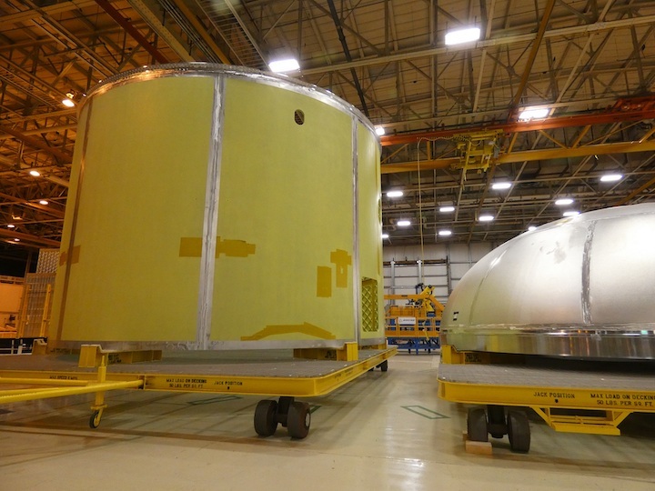
(Photo Caption: The Core Stage-2 engine section barrel sitting in storage next to one of liquid oxygen (LOX) tank domes in February, 2018. The barrel is built from eight friction-stir welded panels and an L-ring on top that serves as the structural interface to the rest of the stage. The vertical weld lands for the panels can be seen here as breaks in the pre-welding primer treatment, along with the circumferential weld land for the ring at the top.)
He gave a hypothetical example: “We have an electrical cable that is say seventy-five feet that runs from one side of the barrel over and up and through and all the way around to the other side of the barrel. That’s a lot of labor to unfurl that cable around, put it in place, and get it just right.”
“Well, maybe it’s smarter to put a production break in there, so you have something smaller to deal with,” Nicholson explained. “You can just physically handle it faster and more readily and easily.”
“We’re implementing some of that, we’re biting that off in small chunks because the more you cut the cable up into shorter lengths you have what’s referred to as line loss, your current doesn’t hold all the way through. So we’re being very strategic about those kind of changes, but we are doing a little bit of that.”
In addition to efficiencies based on streamlining the work sequence, the quality of the work is improving. More work is being completed to its specification, which means less time is necessary to fix the output, fix the specifications, or both.
“Those three big things, incorporating total lessons learned, attacking the electrical system, and pre-integrating the thrust structure ahead of the way we did it in Core Stage-1 are gaining us leaps and bounds on efficiency,” Nicholson said. “Our non-conforming conditions, I don’t know the number but we’re light years down, ten-fold down from where they were in Core Stage-1.”
“And so our expectation is that Core Stage-2 and onward obviously our efficiency will go up a curve and then eventually it’ll plateau. What we don’t know yet is can we forecast that plateau.”
“Our industrial engineering team is off trying to analyze that with all the data from Core Stage-1 and current data on Core Stage-2 to try to help us understand when can we expect to say ‘ok this is as fast as we’re ever going to be able to build a rocket,'” he added. “History tells me — thirty-two years in this business, always building first-time builds, that’s all I’ve ever done — history tells me it’ll probably be the fourth one before we really understand that, but that’s just my opinion.”
Once engine section structural assembly is complete, the unit will be moved out of the structural jig and set up in an adjacent location for the remainder of integration work. In the same time-frame, offline buildup and preparation of much of the equipment that will be installed inside will pick up in the area across the Building 103 aisle at MAF.
“That barrel gets moved to that position and at that time that’s where our plan is to have sub-assembly work done in the right sequence to start bringing in helium tanks, MPS (Main Propulsion System) platforms, and when you get those components in there then you start connecting all the welding, the tubes up to the tanks, to the platforms, and down to the thrust structure to the engines,” Nicholson said. “That’s where our weld team, Vito’s team, will come back in and there will be a massive [block] in the schedule where it’s all about the installation of tubes and welding tubes.”
“That schedule has got us doing that work starting about November of this year into the Winter of 2020, January-February-March time-frame, it’ll be an intensive time for that. That’s when I refer to it as ‘ants at a picnic,’ all the people [are] in the barrel, as many people as we can maximize safely in there to install in parallel tubes and wiring, again to gain that efficiency.”
“A lot of times on CS-1 (Core Stage-1) we had to do that a little more serially,” he added. “We’re striving to do those things in parallel, things like putting one on one shift and one on the other. Maybe work on one side of the barrel, work a couple of quadrants, two of the four quadrants.”
Work inside is divided into four quadrant zones. “Populate tubing over there [and then] while the tube team goes to the other side have the electrical team come behind them,” Nicholson explained. “We’re looking at all those things to gain our efficiencies in our schedule.”
Nicholson said most of the tubing is already at MAF, with delivery of other parts scheduled closer to planned need dates. “I don’t have the percentages with me but we have a good bit of our tubes here,” he said.
“The sub-assemblies, that’s not scheduled to come in until the middle of football season, so Halloween, November, December. That work is planned out, I would refer to it as a ‘just-in-time’ kind of a delivery sequence and that’s where the program is. This side of the build location we refer to as Area 20, that’s where we do sub-assembly work, the helium tanks, the MPS platforms.”
“NASA programs typically run their qualification programs and their first build programs in parallel so there’s that healthy tension between ‘get your qual program done, get the first build done’ and oh by the way if there’s another unit coming you’ve got to feed parts for the second unit,” he explained. “The qualification program is coming to a close so we’re anticipating those parts for Core Stage-2 will come right behind it into the factory.”
“It’s looking like it’ll sequence out correctly for the demand of the factory this Winter, this coming Winter of 2020.”
Other element work also proceeding
While structural assembly work on the engine section continues, the other Core Stage-2 elements are moving from structural assembly to integration. Structural assembly of the intertank was completed earlier in the Summer and the element was moved across Building 103 to complete its standalone work.
After removal from the intertank structural assembly jig on the east side of the building, the element was carried over to Cell G in Building 114 for the two-phase application of spray-on foam insulation (SOFI) on its exterior. The forward skirt recently finished its time in Cell G, receiving a coat of primer paint for rust-protection first, then a coat of SOFI for thermal protection.
The forward skirt is the least complicated element of the Core Stage, and it was the first to enter the integration phase of its standalone work. Once the intertank SOFI sprays and trimming are complete, it will be moved to nearby Area 55 to start integration of all its internal tubing and equipment.
Major welding for the stage will be complete with one final task, attaching the aft dome of the liquid hydrogen (LH2) tank to the rest of the structure. Steven Ernst, Boeing’s Core Stage Engineering Support Manager, said that last weld in the VAC in Building 110 will follow breakover of the Core Stage-1 engine section for its final assembly.
“The manual fixture has been installed on the in-feeder, the arms [are] now in the deployed position, so once we get through the engine section, we’ll bring the dome in here, bring the in-feeder out, get that dome rotated over, move it up into the weld position,” he said recently. Following VAC welds, the LH2 tank will go to Area 6 for plugging of the friction-stir welds and then out to Building 451 to proof test the welds.
Applying TPS improvements, evaluating others
The liquid oxygen (LOX) tank completed its hydrostatic proof test in Cell F of Building 110 earlier in the Summer. The tank is back in Area 6 where non-destructive evaluation (NDE) of its welds was conducted. The welds are imaged after they are completed and after they are proof tested for comparison.
The next step for the LOX tank is to go back into Building 110 for the inside to be washed out with water in the internal clean cell, Cell E. That cell is currently being reactivated to clean the insides of both propellant tanks. After the LOX tank is cleaned, preparations will begin to do the primer and SOFI sprays for it in Cells P and N of Building 131, respectively.
Application of the SOFI thermal protection system (TPS) to the two propellant tanks is another area that NASA and Boeing are looking to make more efficient. One of the process upgrades going through final development and verification is automating the application of SOFI to domes of the tanks, which was actually the original plan but was set aside a few years ago for the first flight article tanks in favor a manual process.
“It was a very laborious process to hand spray those domes but it worked, we met requirements, and it did everything we wanted it to do, it just took a long time because there’s not a very elegant way to do it,” Michael Alldredge, NASA SLS TPS Team Lead, said. “It’s just kind of a brute force thing you’ve got to get in there and do, especially the post-process trimming.”
“We always had in our hip pocket this desire to go back and finish out what we had started a couple of years ago and that was to automate the dome spray procedure. Right now we have the pathway for the robot head to travel and then we’ll actually start doing live sprays in a couple of weeks, but that’s all a part of the verification and validation of the automated spray process that will further allow us to get schedule out of the Cell N processes.”
“We’re pushing to go live with that for Core Stage-2,” Alldredge added. NASA and Boeing are also looking at other changes to TPS composition and application processes, but evaluation of those alternatives is more dependent on analyzing data from the test-firing at the end of the upcoming Stage Green Run campaign and first launch to feed into thermal heating models.
Quelle: NS