
4.04.2024
NASA, Lockheed Martin working to resolve Artemis II Orion issues, deliver spacecraft around summer’s end
NASA is working with Orion spacecraft prime contractor Lockheed Martin to resolve a handful of issues that came up late last year during ground testing, forcing the space agency to delay the launch readiness target date for its Artemis II circumlunar mission to September 2025. The Lockheed Martin assembly, test, and launch operations (ATLO) team at Kennedy Space Center (KSC) is reinstalling some electronics and implementing workarounds for others affected by an electrical circuit flaw found in digital motor controllers on the spacecraft.
While a resolution to that issue appears to be getting closer, the Orion program and contractor teams are also working through the corrective actions process for a problem with how the Orion batteries handle the shock of an extreme abort case. Resolution of both issues will be necessary to allow Lockheed Martin’s production team to move towards finishing assembly and test of the spacecraft before turning it over to Exploration Ground Systems (EGS) for Artemis II launch processing. Currently, the teams are working to meet the EGS handover milestone around the end of summer this year.
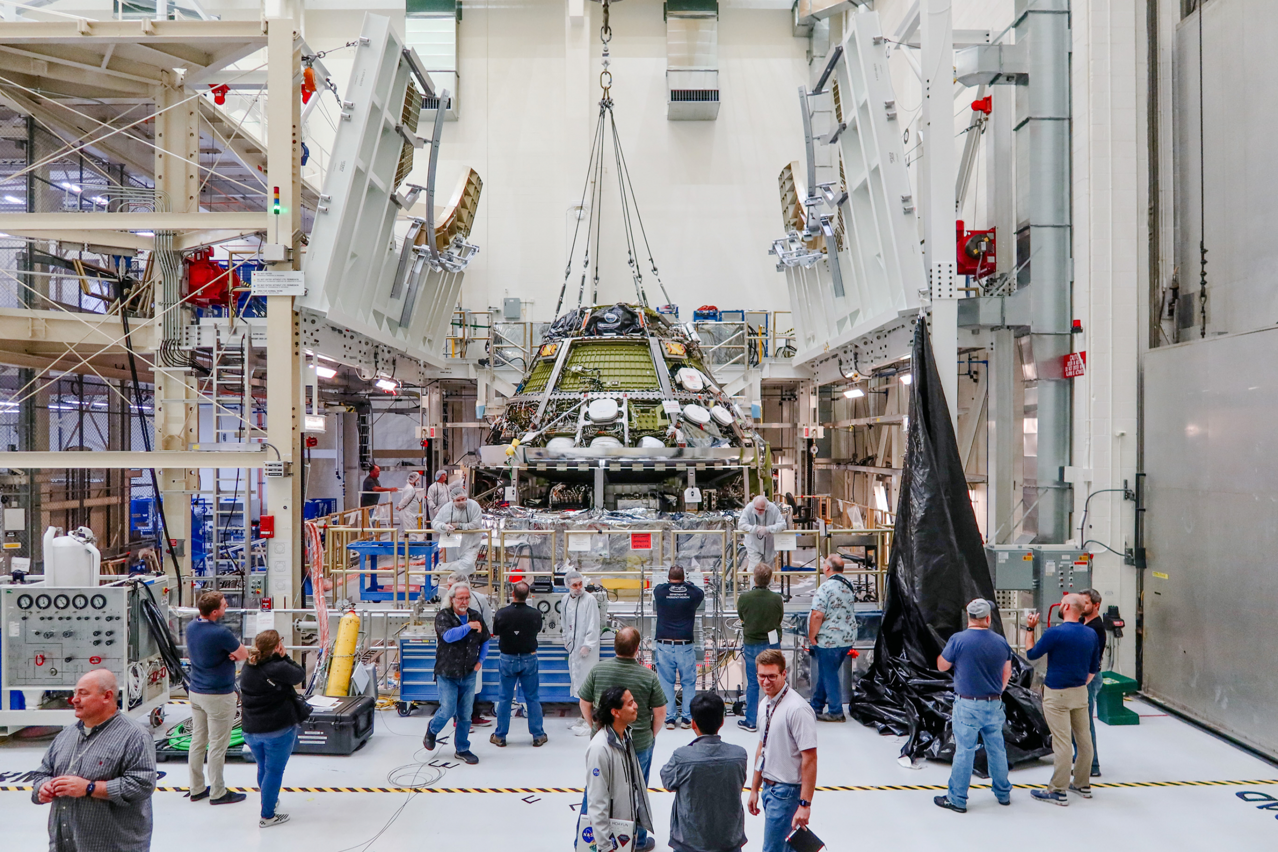
Photo Caption: The Artemis II Orion crew and service modules are mated in the Neil Armstrong Operations and Checkout Building at KSC in October 2023.)
Installing electrical circuitry fixes, implementing workarounds
Since completing the Artemis I mission to the Moon in December 2022, NASA has been aiming for readiness to launch Artemis II on a lunar flyby mission at the end of 2024. However, old and new issues have delayed that target date to September 2025. Artemis II will be the first crewed mission for the Exploration Ground Systems (EGS), Orion, and Space Launch System (SLS) programs, with the four-person crew of astronauts preparing for a 10-day circumlunar flight.
NASA noted in March 2023 that it was investigating the liberation of some material from Orion’s base heatshield during the Artemis I re-entry to Earth’s atmosphere. That investigation is expected to continue through the spring of this year. Two new issues with Orion came up near the end of 2023 that are also factoring into the delay, one with the design of a spacecraft electronics circuit and one with the durability of the batteries to withstand the forces of an extreme abort case.
“At this point, we drove that September [2025] date based on the time we think it’s going to take to do the removal [and] replacement of the life support system electronics and the penalty testing required to do the integration on the way back out,” Amit Kshatriya, NASA deputy associate administrator for the Moon to Mars Program, said in the Jan. 9 audio conference with the media announcing the delay. “We’re hopeful that the other findings that are as a result of abort loads on the battery, as well as the conclusion of all the tests required for the heatshield, is enveloped by that work.”
Rescheduling the assembly, test, and launch processing timelines has to take into account not only the time to fix the issues, build new parts assemblies, and reinstall them but also the time needed to retest everything that needs to be undone and reconnected for those reinstalls.
“Since the [media audio conference in January], we were working through the resolution on the motor control side and completely finishing up the battery investigation, so they’re both proceeding well,” Kshatriya said in a March 22 interview with NSF. “I would say there’s nothing I’ve seen in the recovery plans or the test plans that would give me any pause that we’re not going to be able to hold that date that we pushed out in January, with some margin.”
The issue with the design of an electrical circuit was found during acceptance testing of an air ventilation and temperature controller (AVTC) unit that was assigned to the Orion spacecraft in production for Artemis III. The electronics in particular are used to command motors that control the position of valves in different environmental control and life support systems (ECLSS).
“What they do as a part of acceptance is they do an overcurrent test to make sure that the motor circuitry’s internal circuit protection is intact, so we can deal with an overcurrent,” Kshatriya explained. “That condition was stressing to this particular design flaw, because the way you do that is you put a really high output current and really kind of severe voltage on the output of the motor and so that kind of gives you a stressing ‘back EMF (electromotive force)’ case. In that particular case, [the part] just hard failed, like right off the bat, and so that’s where it was like ‘whoa, what happened?'”
“The circuit that was impugned was a motor drive for [a direct-current] motor,” he added. “In any electric motor drive design, you have to take into account when the drive circuitry is in communication with the output of this motor, you’re going to get ‘back EMF’ from whatever you’re driving.”
“These parts are rated to get reverse voltage, that’s not the issue, what you want to make sure is that you don’t do it in a way that exceeds the part rating and so we found some errors in that design that was allowing stray voltage to linger on that side of the circuit. The fix is pretty simple, you basically…mount some capacitors and resistors to wash that voltage out, so that’s why it was so easy to turn around.”
“Now, when you [do that] you’ve got to be careful about how you re-accept it,” he explained. “So, we’re re-accepting and doing a full acceleration of [vibration] and all of the [qualification and acceptance testing] on the new cards.”
“They finished all that work in the last three months, did the re-acceptance, shook it, did all the thermal sweeps, screened it for workmanship, and it’s over there at KSC.”
The circuit is common to digital motor electronics in ECLSS controllers in different locations on the crew module (CM) and crew module adapter (CMA). Some of the electronics boxes are hard to reach, but their life support functionality is so critical that the bad circuits had to be fixed and replaced.
In other cases, the risks could be mitigated with operational workarounds. “We went through kind of [an assessment of the] disposition, system-by-system, where these circuit cards exist and there are a couple of cases where you can’t get there, in terms of [justifying] use as-is, and you have to [replace them],” Kshatriya explained. “A couple of them you can [apply workarounds] because of the margin we have in the thermal system.”
Fixes were implemented for digital motor controllers in the AVTC box for carbon dioxide (CO2) and humidity control (CHC) valves and also for circuits in an oxygen regulator assembly (O2RA) controller.
“[For] the CO2 controller and the O2 regulator, those are kind of like ‘must-work’ anyway,” Kshatryia said. “Even if you have good confidence that whatever unknown defects are well-bounded, and you have redundancy, you still have to fix it because it’s in direct communication with the crew.”
“So, it didn’t matter what the access was for those, we were just going to go after it anyway, because there’s no real workaround. We have a lot of cases where we want to make sure we can deal with all sorts of contingencies, in terms of depressurization, etc., so these are all must-work, and we just have to go fix it. The thermal control ones [were] a little more fungible, [and the] cabin fan was kind of the same way.”
The remove and replace (R&R) of the AVTC boxes was challenging because it would require a significant amount of breakdown and disassembly of wiring and other equipment inside the crew module. However, the Orion team came up with a workaround to bypass a lot of that disassembly by leaving the existing box in place and mounting the replacement in a different location.
“We’re essentially bypassing it, the current config, so we’re not taking out the old controller, because it’s so far buried in the ECLSS bay,” Kshatriya said. “We’d have to do a bunch of ‘penalty’ testing on the way back out as we broke all the connections and then back in again, so we just decided to mount the replacement in a different location and bypass the current controller that’s in the spacecraft.”
The fully mated Orion “short stack” for Artemis II is currently in the Final Assembly System Test (FAST) cell in the Neil Armstrong Operations and Checkout (O&C) Building at KSC. The crew and service modules were mated last October, with the service module (SM) already mated to the Orion spacecraft adapter cone. The Lockheed Martin ATLO team is performing integrated testing of the spacecraft in the FAST cell, in addition to the electronics maintenance and repair work.
“The hardest one to deal with was the AVTC, the CO2 humidity control valve, that’s the one that requires offloading and the de-integration of some of [the internals], but they mitigated a lot of that by implementing this bypass solution. They have to break some connections and they had to do some work on where to mount it in the spacecraft because it’s a new mounting location.”
“You want to make sure all the environments are attenuated by the position, so we had to go through that exercise, but that didn’t require a lot of hardware to be removed, that was primarily analytical work,” he added. “So that’s where we are there, the team has already turned around the fix. The hardware is in hand and if I’m not mistaken, they’ve already gone after the O2RA controller and they’re going to go after the bypass next.”
“If it’s not already at KSC, it’ll be there in the next few days, to go do that work.”
For other valve controllers affected by the electrical circuit flaw, like the flow control valve, it was possible to implement an operational workaround. Kshatriya explained that the related controller is in the crew module adapter and is inaccessible while the crew and service modules are mated. “[The flow control valve] is the interface between the internal and external cooling loops,” he said.
“[It’s] in the crew module adapter, which is kind of the most odious to access, that would require destacking the CM and the SM. Fortunately, that’s the one that we can just peg at a fixed position, and that gives you full capability in terms of thermal control, and we have redundant valves in the circuit that allow us to modulate that control.”
“I don’t know the exact value, but it’s at some intermediate position,” he added. “We [would] de-energize the valve and would just allow nominal flow, almost like a bulkhead feed-through, so that one we don’t need to worry about it, because we were worried about it enough to make sure we had the right thermal analysis. We went through all that and convinced ourselves it was fine.”
The Artemis II electronics boxes that had circuitry with the same design had passed the acceptance test that the AVTC box for Artemis III failed. Kshatriya said that the electronics boards came from different suppliers.
“Especially when you’re doing EEE (electrical, electronic, electromechanical) parts, these junctions, there’s a lot of lot variability in these parts that you get,” Kshatriya explained. He said the failure occurred in “a PNP (positive-negative-positive) junction I think it was in a MOSFET (metal–oxide–semiconductor field-effect transistor).”
“[The electronics board for the Artemis III box] that failed during [the] test was a different manufacturer, different lot, so there was what we call parts separation between the two boards, even though the design was identical. With these boards, it could very well have been we just got some really robust components for the Artemis II board and then when we cut in the other ones, they matched the spec but every once in a while, you just get a great part, and you know you can prove this to yourself.”
“And in fact, we are doing this also, because this is what we do, we love data,” he added. “We have these parts on the ground, still, from the same lot, in the Artemis II config. Our EEE parts guys and our avionics guys are some of the best in the world, so they’re going to run a fleet leader test and just bang away at these things and see what happens.”
Looking at improving new batteries to handle extreme abort shock
The issue with the Orion batteries came up more recently. Rather than in an acceptance test, it was during a qualification test in December. A part of certifying the human-rating of the Artemis II Orion configuration is verifying that it meets all the requirements for abort scenarios.
The qualification test was performed at the component level, subjecting the battery by itself to the loads of a sudden, intense shock that it might see in an extreme launch abort case. “What we saw in the qualification test was we subjected that battery to the full separation shock that we would expect for the spacecraft coming off of the launch vehicle under the worst possible loss of control and in that case, we saw a loss of, in some cases, connector connectivity,” Kshatriya said in the Jan. 9 audio conference.
“The concern would be not that the vehicle would be able to abort safely off of SLS, but that we would be able to maintain all of the power margin that we need for the vehicle from that separation all the way through landing.”
The batteries on Orion for Artemis II are a new design that incorporates more safety features, given that all future flights of the spacecraft are expected to be crewed beginning with this mission. The battery design that flew on the uncrewed Artemis I Orion was floated as an alternative during brainstorming early in the process after the problem came up but was quickly ruled out.
“The Artemis I design was a large cell battery, high capacitance,” Kshatriya said in the NSF interview. “[It uses the] same material but did not have all of the mitigations that we’d like to have on a human-rated vehicle.”
“We accepted that for [Artemis I] because we didn’t have to deal with the loss of crew risk, so we let that battery design fly. [The] Artemis II batteries have all the safety [features], like small cell, isolated cells, all of those protections built in to prevent a thermal runaway.”
“That’s not the only thing you do to prevent that kind of thing, but bottom line is that we like the Artemis II design because it’s way safer for the crew,” he added. NASA and Lockheed Martin are looking at different options to resolve the battery issue.
“In terms of the options that are still remaining, I think they have a good understanding of the environment and what in the design is causing the off-nominal vibration response and so there’s a couple of things that they’re working through in terms of either a repair, in-situ, of the existing batteries, or an acceleration of the Artemis III shipset,” Kshatriya said.
While the options for which battery set to use are evaluated, the repaired battery design will still need to complete crew-rated qualification testing for Artemis II. “Lockheed and [the battery vendor] EaglePicher and the Orion Program and all of our tech authorities are pretty heavily engaged in this test program,” Kshatriya said.
“After the fixes [are implemented] and you do [the stress] and the vibration analysis, you have to go in [and test]. You have to not only do it analytically [and] convince yourself in all regimes you’re good, but you have to get these things on shaker tables and make sure that the fix works.”
“We’re going through that — so far, so good,” he noted. “We’ve exposed the repaired batteries to what we believe to be equivalent environments, [the] same kind of test profile as before, for the ones that we saw in December. So that’s in good shape, the remainder is how are we going to cut these back in and then how is it going to cut back into ATLO … the program is still working through [that].”
Vacuum test is next major milestone, working towards EGS handover around the September timeframe
Before the announcement of the delay in January, the next major milestone in Artemis II Orion production was a vacuum test of the spacecraft in the O&C Building using one of the Apollo-era altitude chambers that was recently renovated for Orion. Kshatriya said they could proceed with two such tests first and then implement the battery fix afterward.
“There’s an EMI (electromagnetic interference) and EMC (electromagnetic compatibility) [testing] and then vacuum testing and we can do that and take credit for almost all of it and do penalty testing afterwards, and that’s primarily on the battery side,” he said. “If it’s not already done, I think they’re pretty much done with that [ECLSS electronics hardware] rework, so that’s not really going to be an issue but the battery side of it that we did talk about a lot, can we get it out of the FAST cell and into the chamber with the current batteries.”
“The technical community convinced themselves that even for integrated EMC and for vacuum [testing], you’re good to go. So, we will have to de-integrate and go swap [the batteries after those tests] but there’s ways to penalty test different components there to make sure you’re not compromising the integrity of the spacecraft-level tests.”
The batteries are located on the Crew Module outside the pressurized crew compartment.
Kshatriya said the program is currently targeting completion of Orion and handover to EGS in September. “Right now, we’re trying to make sure we can do the final handover by the September timeframe, that’s the target,” he said.
“We have to make sure we settle on what the battery solution is going to be, so there is a fair bit of uncertainty there. I think we’ve accounted for it in the risk for the overall schedule; for the [September 2025] launch date, I think that risk is covered.”
NASA says the spacecraft will be moved from the FAST cell to the altitude chamber in April to prepare for the EMI/EMC tests first. Vacuum testing in the chamber is currently scheduled for early July.
Quelle: NSF