

One of the major milestones for allowing humans to fly on NASA’s Orion spacecraft is currently undergoing test preparations on the Space Coast. The Ascent Abort Test (AA-2) aeroshells have undergone fit checks at its LC-46 launch pad before being transported around the Kennedy Space Center (KSC).
Fits checks and transport runs ahead of AA-2 test
The test will launch from Launch Complex 46 (LC-46) at the Cape Canaveral Air Force Station (CCAFS) in Florida – currently scheduled to take place in April of next year.
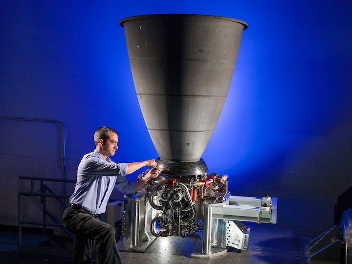
An Orbital ATK SR 118 rocket motor is the booster for the test. Its original purpose was as the first stage of the Peacekeeper Inter-Continental Ballistic Missile (ICBM). The Peacekeeper program was deactivated in 2002 and today the motors in the inventory are used for civil purposes such as space launches.
The Aeroshells are essentially just an adapter between the Orion simulator and the Peacekeeper motor. However, because the Orion is much larger than the Peacekeeper motor (5 meters vs 2.7 meter), the aeroshells act as an adaptor.
When the entire stack is integrated, the Peacekeeper motor will fit at the very center while Orion with the Launch Abort System (LAS) sits on top.
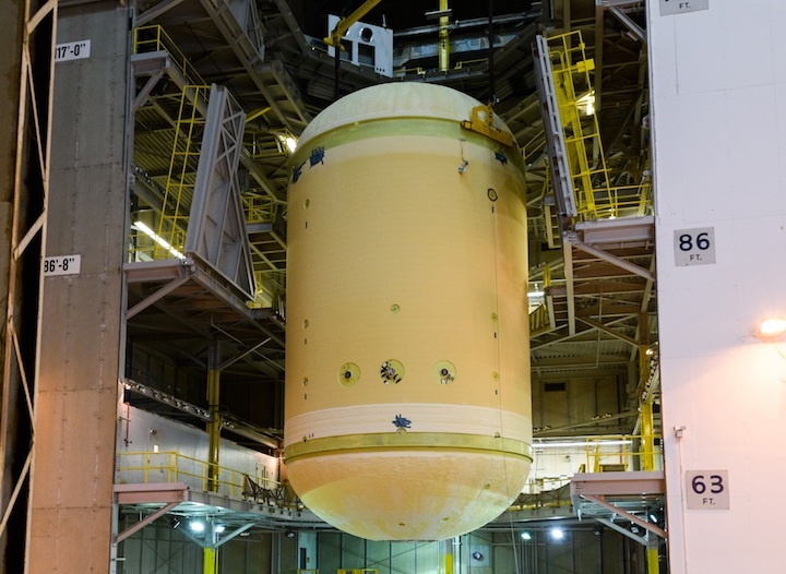
The aeroshell was shipped in three parts from EMF Inc. on nearby Merritt Island before being mated – via bolts – in High Bay 4 (HB-4) of the Vehicle Assembly Building (VAB).

Aeroshell for AA-2 arrives in the VAB – via NASA
Integration will come later in the processing flow, which will involve the Peacekeeper booster, the Aeroshells, the LAS and the Crew Module Boilerplate Orion coming together ahead of launch.
The CM is currently undergoing final testing at NASA Glenn’s Plumbrook facility ahead of returning to the Johnson Space Center (JSC) to be integrated with its Sep Ring. It was on show to the media when it was previously at JSC.
To take advantage of the Aeroshell already being mated at KSC, it was loaded on to a truck for a trip to next-door Cape Canaveral Air Force Station (CCAFS).

Photo of the pad fit checks, by Mark Kirasich.
It was then loaded into LC-46 for fit checks, providing a view of what the aft end of the test vehicle will look like ahead of launch.
Located at the Cape’s most easterly point, SLC-46 is one of Cape Canaveral’s youngest launch complexes. It was built in the 1980s to support testing of the US Navy’s Trident II submarine-launched ballistic missile (SLBM) and most recently launched Minotaur rockets.
The Aeroshell was spotted again on Monday, this time back at the Kennedy Space Center, being worked on next to the vacated work site for the Space Launch System (SLS) Mobile Launcher (ML) which is now inside the VAB following its rollout to 39B.
It is not clear what the current work on the Aeroshell involves, although it could be under preparations to re-enter the VAB to await the arrival of the final elements of the AA-2 vehicle.

Diagram of AA-2 test vehicle, left. Diagram of Orion LAS, right. Credit: NASA
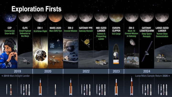
That test will be a major milestone for crewed launches on Orion. The first launch of Orion came in 2014 with the Exploration Flight Test -1 (EFT-1) test that successfully sent Orion on a test flight after being lofted by a ULA Delta IV-H.
The first launch with SLS will come in 2020 when the Exploration Mission -1 (EM-1) sets sail from Pad 39B at KSC. The first crewed mission will be during EM-2, around 2022, for a trip around the Moon.
AA-2 will test the in-flight abort ability of the LAS, which is designed to pull the Orion – and her crew – away from a failing rocket. During the test, the abort will be triggered when the vehicle is traveling at approximately Mach 1.3 at an altitude of around 31,000 feet.
SpaceX Dragon 2 will also be conducting an Ascent Abort test with the same goal of proving they have the capability to safely abort from a failing booster.
Quelle: NS
---
Update: 2.10.2018
.
Navigating the twists and turns steering SLS Development
This year’s decision to increase and extend use of the initial “Block 1” operating configuration of NASA’s Space Launch System (SLS) booster also impacts the space agency’s near-term plans for evolution of the launch vehicle’s design.
The Congressional commitment to a second Mobile Launcher for SLS, along with the ability of SLS Block 1 to carry out early Orion lunar test flights and send a six-ton spacecraft to Jupiter has engineers back at the proverbial drawing board to look at re-assigned missions and preliminary vehicle configurations.
The design and analysis work that comes with the latest change in direction is above and beyond work that was well underway for the second generation SLS vehicle called Block 1B, and the SLS Program is looking at how to juggle schedules to finish all the new Block 1 work so it can fly before Block 1B.
Iterative design process
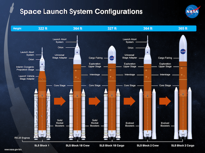
Currently forecast to fly in 2020, the first SLS launch will begin Exploration Mission-1 (EM-1), sending NASA’s Orion spacecraft uncrewed to the Moon for a multi-week Lunar orbit mission. SLS will fly EM-1 in its initial Block 1 configuration which has the Interim Cryogenic Propulsion Stage (ICPS), a modified United Launch Alliance (ULA) Delta 4 upper stage, stacked on top of its foundational elements of two five-segment Solid Rocket Boosters (SRB) and a liquid-propellant Core Stage using four RS-25 engines.
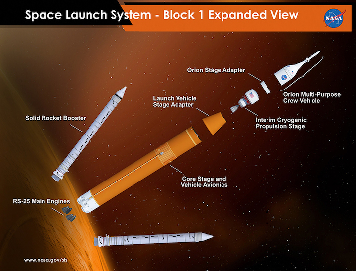
Already receiving funding, longer-term plans are to develop the Block 1B vehicle which replaces Block 1’s ICPS upper stage with a more capable one called the Exploration Upper Stage (EUS). EUS has four RL-10 engines instead of one in the ICPS, and also has higher capacity liquid hydrogen and liquid oxygen tanks sized to the 8.4-meter/27.6-foot diameter of the SLS Core Stage.
Design and development of SLS vehicles is being done in phases or configuration “blocks.” An iterative design process is used by the program to take a vehicle configuration from a preliminary concept to hardware that is certified for flight.
“I think the key is the design analysis cycle, the DAC,” David Alan Smith, SLS Utilization and Payload Integration Manager with the Spacecraft Payload Integration and Evolution (SPIE) Office, said. “That’s the period of time where we perform, with increasingly mature data, analysis cycles on the performance of the vehicle, the accommodations, the interfaces, the operations. That’s really what the DAC means.”
“Now there’s a whole bunch of DACs, because [as] a vehicle configuration matures we have additional DACs. They go off into infinity potentially, [but] we have one to maybe even three DACs depending on what we do.”
“The design analysis cycles are intended to mature the vehicle from pre-PDR (Preliminary Design Review) through CDR (Critical Design Review) and after which you get into your verification analysis cycles (VAC) which feed into your design certification,” Rob Stough, SLS Utilization Manager with SPIE, explained.
Outside of that, other people look at future payload utilization for SLS. “[That] was developed as a way to more quickly with a different set of people and resources look at how can we best utilize the vehicle, how can we look at how the performance can best be used or optimized,” Smith said.
“The vehicle configurations have kind of been defined, but there are still kind of crazy trade studies that we do looking at performance, accommodations, [and] interfaces.”
“[That] analysis lives more in the conceptual realm that feeds requirement generation that starts the initial DACs,” Stough added.
The Block 1 Crew vehicle configuration, which will fly with the Orion crewed spacecraft, is currently into Verification Analysis Cycles. The first mission it will fly is EM-1.
“There’s certifying the vehicle for a capability, you can consider that what you do at DCR, Design Certification Review, then after that you have to get ready for flight, so you would then perform a FRAC, Flight Readiness Analysis Cycle,” Stough said. “That generates all the flight products that you would feed your I-loads (initialization loads), everything for flight.”
“One (DCR) is certification of the configuration called Block 1 and another (FRAC) would be the readiness of a mission called EM-1 using the Block 1, two different flavors,” Smith added. “If you went to Boeing and bought a 737 that would be like a Block 1,” he explained.
“Well no one in history has ever flown a 737 — they’ve flown a Delta 737 or an American Airlines 737. It’s a configuration that gets customized out of the factory for whoever buys it. So Block 1 in its pure state is a capability like Rob said, but it’s going to be fiddled with a little bit for a particular mission.”
“Europa (Clipper) is going to take the Block 1 and go to Jupiter, EM-2 (Exploration Mission-2) is going to take the Block 1 to do a test flight with humans,” Smith continued. “And then going to Block 1B, we’re going to do the same thing.”
The EM-1 vehicle will have a number of customizations, some because it’s the first SLS flight vehicle. Most visible are the photogrammetry markings on the SRB cases on the +Z side of the vehicle, but a significant amount of one-time Development Flight Instrumentation (DFI) sensors are also being placed on the EM-1 vehicle.
Data from pressure transducers, accelerometers, and other types of sensors embedded on the skin of the Core Stage and other parts of the vehicle will be collected during the EM-1 launch and downlinked in real-time along with operational data.
FRAC-0 for the EM-1 mission is currently being timed to start after completion of integration of the first Core Stage’s engine section. That critical production milestone for the first vehicle is forecast for somewhere in the first quarter of 2019.
History: three decisions
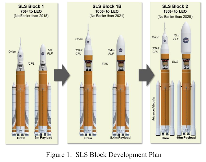
Prior to the initial definition of SLS Block 1 in September, 2011, and in all appropriations bills passed by Congress since then, the vehicle was expected to evolve from Block 1 to its required full capability, which continues to be defined as being able to lift 130 metric tons to low Earth orbit (LEO).
While detailed design analysis on the Block 1 configuration was going on, the SLS Program was also evaluating evolution strategies that would upgrade upper stages and/or boosters. The first evolution, Path A, looked at putting multiple upper stages on top of the Core Stage and Boosters in a Block 1A configuration.
“There was a trade that looked at what if you didn’t do the upper stage you just did the Advanced Boosters, but essentially Block 1A delayed an Advanced Boosters still to Block 2,” Smith said. “There were trades that looked at the booster first but the stages were too important, the upper stages were key to our success.”
“What happened was coming off of Ares we had these J-2X engines and we were kind of looking at an upper stage based on J-2X and it was really a great performer, it looked great,” he added. “However to meet its full potential it had to have a third stage.”
“We called it the CPS, Cryogenic Propulsion Stage, but essentially it was the third stage. That was a great performer but there were two issues.”
“One is it took up a lot of fairing space that the payload needed,” he continued. “You had this big third stage and it was cryogenic and it had to be fueled on the pad and so forth. But the other one that was really the kicker was that we had to develop a third stage and that’s a lot of money.”
“When you think we’re developing the Exploration Upper Stage right now, that’s a costly endeavor this giant stage, the biggest ever made of an upper stage,” Smith added. “Think about having to do that for a second time for a little brother version that goes on top of it.”
“So we traded that performance and that development path to all of sudden we came up with a path that said we’ll use four RL-10s and now we’ve got a stage that really does both functions of what the original J-2X upper stage was going to do and its potential third stage CPS.” That second evolution path, Path B, put a single large upper stage on top of the Core and Boosters in a Block 1B configuration.
The first decision was to choose the evolution path to Block 1B, setting aside the Block 1A possibilities. “When you look at it, as you’re seeing our DAC, VAC, and FRAC cycles that we’re talking about, every time you develop one of these guys you’ve got to do all that over again,” Smith explained.
“There’s a lot of money and a lot of people and so it ended up being a pretty easy trade to say we’re almost getting our performance with a Block 1B configuration using the EUS that we could have gotten with that original Block 1A at a smaller cost and a shorter time frame and less risk.”
“That trade worked out well, we got rid of a stage in a sense going Block 1B,” he added. “The complexity, the cost, the staging, the manufacturing, we were able to eliminate that from the path.”
Current public estimates say the Block 1B configuration can place 105 metric tons in LEO; in order to reach the 130 metric ton mandate, SLS has been studying a future evolution of the vehicle called Block 2. The assumption is that along with improved boosters replacing the Shuttle-derived SRBs, a major redesign of the vehicle would be necessary to get the required performance.
Both efforts would be expensive and with Block 1 and Block 1B still yet to fly, development of Block 2 is not currently funded.
Although the Block 1B configuration had become favored over Block 1A by 2014 to follow Block 1, NASA still needed to get the authority and funding to begin development. Originally, the Block 1 vehicle was the only configuration authorized and funded and initial launches were studied using ICPS.
NASA finally got the go-ahead with the decision by the 114th Congress to develop EUS and the Block 1B vehicle beginning with enactment of the Fiscal Year (FY) 2016 budget in late 2015.
Shortly thereafter in late January, 2016 a formal directive was issued by Exploration Systems Development (ESD), which integrates the Exploration Ground Systems, Orion, and SLS Programs, to stop all work on Block 1 after the single EM-1 launch. All subsequent SLS launches would use the EUS and Block 1B.
The directive to concentrate on EUS and Block 1B after EM-1 stopped detailed design work on Block 1 concepts, including Europa Clipper studies. With that, not only was ICPS human rating work for EM-2 (the first crewed Orion flight) suspended but studies of launching Europa Clipper on SLS then focused solely on using the more capable Block 1B, which also provided more performance margin for a launch on a direct trajectory to Jupiter.
“NASA has always wanted the Block 1B because it’s a great performing vehicle and so when we went to Block 1B formally…all of sudden we started looking at a cargo version of Europa on a Block 1B,” Smith said.
At the time, a single Mobile Launcher (ML) was enough to satisfy the long-term goal of one flight per year for SLS and Orion; however, ML was going to require a significant teardown/disassembly and reconstruction to support the longer, EUS-based Block 1B vehicle, along with structural reinforcements to handle the higher weight of both the vehicle and the modified umbilical tower.
It was expected that the program’s only Mobile Launcher would be out of service for nearly three years, a 33-month long period that came to be referred to as an “iron-bar” stuck between EM-1 and the next launch that could not be shortened.
The desire to shorten the time between initial Orion and SLS flights and the availability of additional top-line funding for NASA led to the decision to fund a second Mobile Launcher in the FY 2018 budget.
With funding of the second ML, the first Mobile Launcher, now called Mobile Launcher-1 (ML-1), will remain largely as-is. ML-1 recently completed major construction and after EM-1 it will essentially be ready for additional Block 1 launches.
Another formal directive from ESD was issued in late April moving the EM-2 and Europa Clipper missions from Block 1B back to Block 1.
Change in direction leads to further changes
In order to launch Europa Clipper on Block 1, an additional SLS vehicle configuration is necessary. Early in the SLS Program before EUS was funded, preliminary studies looked at using a cargo configuration of the Block 1 vehicle.
“We did a DAC-0 on that Block 1 Cargo version with Europa,” Smith said. “So that was the first design cycle that said it would work, it could work with a number of different fairings, it didn’t have to be a specific fairing, it was feasible.”
After the change in 2016 to go “all EUS,” the SLS Program was developing three vehicle configurations: Block 1 Crew, Block 1B Crew, and Block 1B Cargo. The SLS crew vehicle configurations fly with the Orion spacecraft launch system on top, which includes the Orion, its Launch Abort System, and aerodynamic fairings and adapters. Cargo configurations use an aerodynamic fairing on top of the upper stage to completely cover a payload package during the early phase of launch.
With Europa Clipper moved back to Block 1, development work on the Block 1 Cargo configuration has resumed. The ICPS is derived from the Delta Cryogenic Second Stage (DCSS) that is used as a Delta IV upper stage, and NASA has also decided to use the Boeing’s payload fairing system for Delta IV in this configuration for Europa Clipper.
EM-2 has also moved back to Block 1 and ICPS, and NASA is planning on leveraging independent development efforts by ULA to human rate the stage. The launch provider is certifying an emergency detection system (EDS) that will fly on the Atlas V launch vehicle for Boeing’s CST-100 Starliner spacecraft.
That avionics, along with the move to Common Avionics between ULA’s Atlas and Delta vehicles will help with human rating, since ICPS uses the same Common Avionics. Some additional modifications such as increased Micro-Meteoroid and Orbital Debris (MMOD) protection are also being looked at for crewed Orion missions that fly on ICPS.
Development work on EUS and Block 1B is continuing with Smith noting they recently finished the DAC-2 analysis cycle for Block 1B, but all the additional Block 1 work and mission design now has to be completed in front of their first launch.
“The timing is a little bit changed since the Spring when Block 1 came back into the mix, so we’ve got to focus on a few more Block 1 missions before Block 1B,” Smith noted. “We have one set of resources that have to do both configurations.”
The EUS PDR was completed in early 2017 and prior to the change in plans the CDR was expected some time this year. With all the changes inserted in the manifest, that timing will also change.
“The Space Launch System Program is assessing the manifest and mission requirements to determine the optimum time to schedule the Exploration Upper Stage critical design review,” said Kent Chojnacki, NASA’s EUS manager for SLS said in an email. “We are examining all the requirements, especially in ensuring SLS Block 1B can send 10 metric tons along with the Orion crew vehicle on a single mission. In the meantime, we are continuing to work on EUS components.”
Quelle: NS
---
Update: 31.10.2018
.
Orion test article completes key White Sands firings for ESM shipment
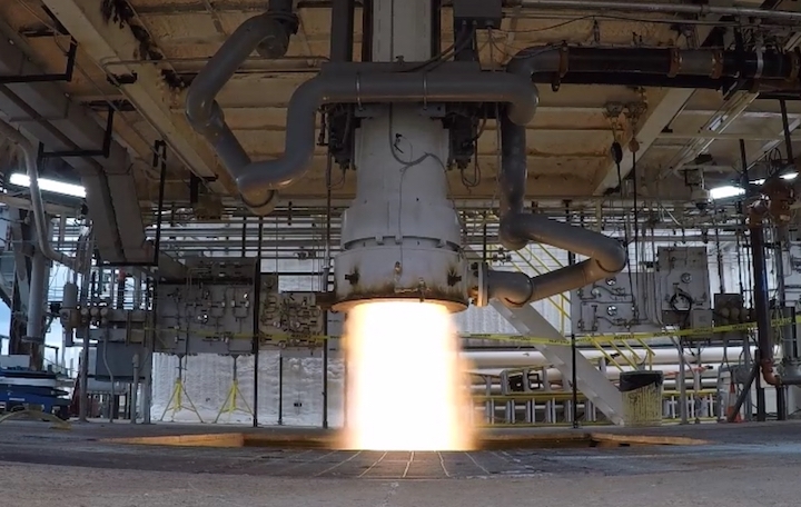
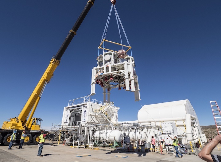
Testing of the Propulsion Qualification Module (PQM) for NASA’s Orion spacecraft resumed at the White Sands Test Facility in New Mexico in mid-October. The test team at White Sands conducted two hot-fire tests critical to shipping the first European Service Module (ESM) from its Bremen, Germany, production site to the Kennedy Space Center (KSC) in Florida some time next week.
The European Space Agency (ESA) chose the two tests to help verify the performance of the propulsion elements of the ESM, in particular active pressure regulation. Results of the tests were good, removing that constraint to ESM shipment.
The PQM, a “battleship” version of the ESM propulsion subsystem, will continue through dozens of tests across two test campaigns now and in the Spring next year.
Hot-fires resume with critical tests to ship ESM
After a year’s downtime, PQM testing resumed with a five-second firing of the test module’s Orbital Maneuvering System engine (OMS-E) on October 13. Three days later, the OMS-E engine was fired again for twenty seconds, completing the two tests necessary to clear the first flight ESM, Flight Model-1 (FM-1), for an overseas flight from prime contractor Airbus Defence and Space’s production facility in Bremen to KSC.
“Those were identified by ESA and they wanted them executed prior to the shipment,” Jim Withrow with NASA’s Glenn Research Center said. Withrow is the PQM Project Manager for the European Integration Office (EIO) at NASA Glenn.
“ESA considered that the highest risk test that needed to be demonstrated, that twenty-second test. And they considered that a constraint to shipment of ESM to Kennedy, so we got that off and it went really well.”
The ESM provides Orion with the capability to fly long-duration missions, including storage of consumables, power generation, and in-space maneuvering. It will fly for the first time on the next Orion mission, Exploration Mission-1 (EM-1), a multi-week flight into and out of a Lunar Distant Retrograde Orbit (DRO).
Built by Airbus DS for ESA, the ESM has three types of engines: twenty-four reaction control system (RCS) thrusters primarily for attitude control, eight auxiliary engines for translational maneuvers, and OMS-E for large translational burns. The PQM has the same set of engines except that it only has twelve RCS thrusters, omitting one of the twelve-thruster RCS “strings.”
Hot-fire testing resumed in Test Stand 301 at White Sands with the full integration of Pressure Control Assemblies (PCA) into the test module. “The supplier of the valves on the PCAs themselves had some challenges to work through before they were delivered for integration into the PCA,” Withrow said.
“Our management team at NASA and ESA chose to prioritize the parts for integration into FM-1 PCAs over the PQM PCAs and that really helped the overall ESM delivery schedule and still was able to complete the two critical tests required by PQM before ESM shipment.”
Overall PQM testing is divided into two steps, Step 1 and Step 2. The two OMS-E tests from within Step 1 required for ESM shipment were moved forward and called Step 1a.
“Both of those tests used the OMS-E and they went exceptionally well,” Withrow said. “They met all of the test objectives that we’re after. They demonstrated that the PCA active control was right on the money, and that was the biggest risk that we were trying to mitigate prior to the shipment of the ESM.”
“It used sufficient propellant so we saw the PCA actively doing its job,” Withrow said of the twenty-second test. “There’s two parts to managing the pressure in the prop tanks.”
“The first one is we call it a PRU, a pressure regulating unit, and it is an electronic controller and it controls the second part of the system that we call the PCA or pressure control assembly and that is the fluidic control hardware and that actually manages the prop tank pressures,” he explained. “And that went exceptionally well.”
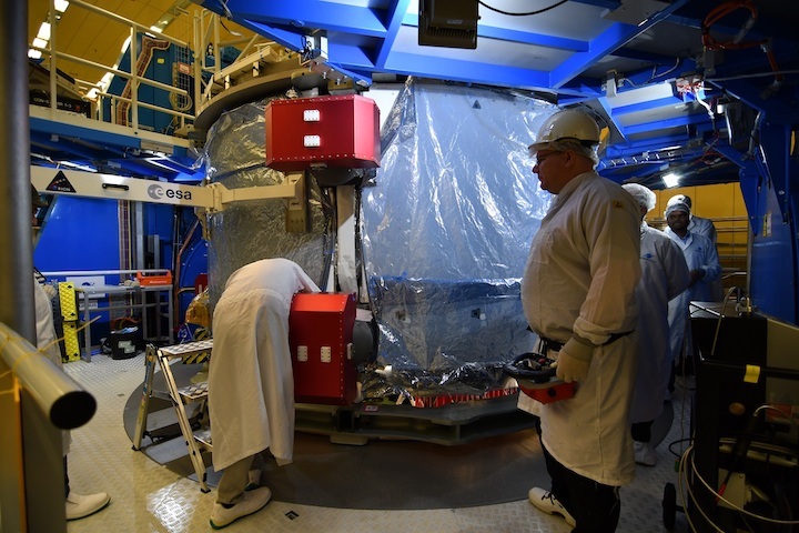
FM-1 has completed functional testing at its Assembly, Integration, and Testing (AIT) Airbus facility in Bremen. One of the last hardware installations was the radiators around the outside of the module, which was completed in September.
A pre-ship review in Bremen is planned for the last week of October, with the shipping flight to Florida the following week. “Airbus has looked at the data that was collected over the first two firings that we’ve had this month and they have done an analysis to characterize the performance of the system and to satisfy the desire for ESA to show that the PCAs work and they were able to do that and provide that data for the pre-ship review,” Withrow noted.
Two campaigns testing corners of the envelope
In parallel with the final assembly of the EM-1 Orion vehicle in Florida, the test team at White Sands will first running the test cases in Step 1. “From the original planning of PQM testing we had two steps,” Whitrow said.
“The primary difference consisted of how the propellants were conditioned for use. Step 1 uses unsaturated propellants and Step 2 uses saturated propellants, so we’ve been sticking with those two steps. We did add a blowdown test, those tests were added as I’m going to call it a precursor to Step 1.”
One of the primary objectives of test campaign is to delta qualify the OMS-E. Although the engines were used successfully throughout thirty years of Shuttle flight operations, Orion has a different flight envelope.
“Our operational envelope for OMS is larger than the Shuttle used for OMS,” Whitrow explained. “We know it went through some qualification tests to get used for Shuttle and we know what those are.”
“We are going to be operating within that original qualification envelope that Aerojet subjected that engine too, but they’re outside of the bounds of what Shuttle used, so we have some delta qual tests that we want to conduct inside a representative propulsion system for the ESM.”
Whitrow said Step 1 will continue with OMS-E tests before the campaign comes back to testing the Auxiliary and RCS engines. “The Step 1a designation was really set up by ESA. Those are the two tests that they said they wanted to accomplish before they ship the ESM.”
“The remaining tests we just call Step 1 and those will encompass the OMS delta qual, the Aux acceptance, and then are a number of crosstalk tests we conduct between the RCS and the Aux. So that’s kind of the balance of Step 1.”
“Overall for the Step 1 tests we’ve completed two of seventeen,” he added. “Two of the twelve tests are behind us, the other ten tests are going to be using just the OMS engine and the Aux engines. We have five tests that have to use RCS and those will pick up after we’ve completed those twelve.”
The test cases will be looking to collect data on how the system performs at the corners and edges of Orion’s operational envelope. “The test sequences are similar to flight like scenarios in some cases and they’re formatted to stress the system with what we’re calling worst-case scenarios and verify the propellant subsystem,” Whitrow explained.
“The easy cases are not really what we’re after when we’re doing this verification, we’re trying to push the envelope and get to the corners of the boxes that we need to verify.”
Overall objectives
The PQM is a “battleship” propulsion test article, with a “beefier” structure and tankage than flight articles. “The overall test campaign that we’re doing with PQM focuses on validating the pressurization function and hot-fire operations,” Withrow explained.
“The test sequences themselves are structured to anchor fluidic models that we’ve got. NASA has their own fluidic models, Airbus has theirs, and I believe that Lockheed may even be developing on theirs. So we have fluidic models that work on the single engine level and the multi engine firing level.”
“For single engine firings we’ve got a lot of data from vendors themselves on the manufacturers of the RCS and Aux engines, they have data on the performance of those, but once you put it into the overall system, we’re trying to understand and anchor the fluidic models for the whole prop system. And so we’ve gotten some really good data in the firings we’ve had to date.”

“Even in blowdown — blowdown gave us a lot of good data and the two OMS tests we’ve had has certainly given us some really good data, too.”
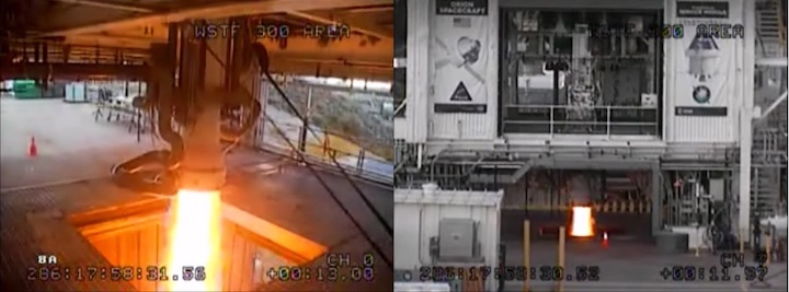
Blowdown testing was conducted in August, 2017, while waiting for the PCA regulator hardware to arrive. “Those tests were where we used larger quantities of ullage and lower levels of propellants, so you had no pressure regulation during that time, so no active control of the propellant tank pressures,” Whitrow explained. “We set the initial prop tank pressures with the facility ground support equipment.”
“We didn’t have any of that during blowdown, we just used the ullage to try to maintain the pressure of feeding the propellants to the thrusters themselves. We really didn’t use large quantities of propellants during that period when we were doing blowdown testing.”
"When we were conducting those tests, we had all three types of engines running, we had crosstalk between the subelements, we had data collected there and some of those tests we don’t plan to reconduct in Step 1 or Step 2,” he added. “So we don’t plan to do any blowdown tests for the remainder of the PQM testing.”
Step 2 next Spring
The Step 2 campaign is planned to begin next Spring using saturated propellant that more closely simulates conditions at the end of a long-duration mission. In Step 1 the propellant is unsaturated as it would be at the beginning of the mission when the propellant tanks are full.
“In flight, you will have an order of maybe three weeks or maybe even longer where you’re going to have this pressurant gas sitting over top of and keeping the prop tanks pressured and what will happen is that gas will diffuse into your propellant,” Whitrow explained. “It takes weeks to occur and once that occurs your performance of the engine will change and the way the system responds will change.”
The Step 2 tests will use propellant that is saturated with the gas that pressurizes the propellant tanks. “When you’re mixing your propellants and you’re expanding that and pushing it into a combustion chamber you can imagine that gas is coming out of solution very quickly — just as like when you open a carbonated water bottle, you see the bubbles immediately appear,” he noted.

ESM FM-1 OMS-E nozzle and Aux engine pairs (with protective covers on) during OMS thrust vector control (TVC) testing at Bremen during the Summer. Credit: ESA.
“So we know you’re going to have bubbles of your gas appearing and we have to test both sides of that, so we test the side where we’re unsaturated, we test the side where we’re saturated and the thrust and the performance of the system can’t be impacted.”
Many of the tests conducted during Step 1 will be repeated in Step 2. “We have a number of tests that we want to conduct in Step 1 with unsaturated propellants and then we repeat those same tests in Step 2 with saturated propellants,” he said. “So really we can only do half of the OMS delta qual with Step 1, the other half is in Step 2.”
There are additional tests planned in Step 2 to look at contingency cases, future flights, and to gather additional engineering data.
“In the Step 2 tests, we have nineteen particular sequences we’re going to run,” Whitrow noted. “Three of those nineteen are not needed for FM-1, they’re needed for FM-2 when we have a crewed mission, so we need sixteen of those nineteen tests completed before we go operational with FM-1.”
“I know there will be additional tests added at the end of Step 2 that NASA and Lockheed jointly have requested on the Aux engines themselves,” he added. “So there’s some additional data that the manufacturer of the Aux engines hasn’t collected. They typically run single engine tests and they’re looking for some additional data with multiple engines running together and PQM is a perfect platform to do that.”

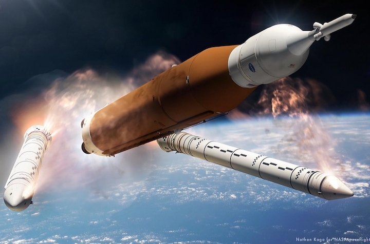
Orion fires its OMS engine to leave the Moon. Credit: Nathan Koga for NSF/L2.
A couple of the additional tests planned for Step 2 include contingency cases that require long burns of Orion’s engines. “One of them is an Abort To Orbit or ATO, that’s going to be using OMS-E and the Aux engines. I know that there’s a Trans Earth Injection (TEI) test that uses I believe the primary engines are the Aux engines with some RCS firing in there.”
An ATO abort would cover launch vehicle failures during ascent that left Orion with too much speed for a splashdown abort in the Atlantic Ocean, but with marginal speed to make it to abort. Normally the upper stage of the launch vehicle handles the end of ascent and orbit insertion.
The ATO test case is currently looking at a 739 second duration hot-fire with 690 seconds of that using all three sets of engines — OMS-E, Aux, and RCS.
The TEI test case simulates a situation where the OMS-E engine can’t or won’t be used for one of the burns to get Orion out of lunar orbit and headed back to Earth. The four pairs of Auxiliary engines would have to make a long burn — in the test case firing with the RCS for 3635 seconds, just over an hour.
Quelle: NS