
.
There has never been anything like the Saturn V, the launch vehicle that powered the United States past the Soviet Union to a series of manned lunar landings in the late 1960s and early 1970s. The rocket redefined "massive," standing 363 feet (110 meters) in height and producing a ludicrous 7.68 million pounds (34 meganewtons) of thrust from the five monstrous, kerosene-gulping Rocketdyne F-1 rocket engines that made up its first stage.
At the time, the F-1 was the largest and most powerful liquid-fueled engine ever constructed; even today, its design remains unmatched (though see the sidebar, "The Soviets," for more information on engines that have rivaled the F-1). The power generated by five of these engines was best conceptualized by author David Woods in his book How Apollo Flew to the Moon—"[T]he power output of the Saturn first stage was 60 gigawatts. This happens to be very similar to the peak electricity demand of the United Kingdom."
Despite the stunning success of the Saturn V, NASA's direction shifted after Project Apollo's conclusion; the Space Transport System—the Space Shuttle and its associated hardware—was instead designed with wildly different engines. For thirty years, NASA's astronaut corps rode into orbit aboard Space Shuttles powered by RS-25 liquid hydrogen-powered engines and solid-propellant boosters. With the Shuttle's discontinuation, NASA is currently hitching space rides with the Russians.
But there's a chance that in the near future, a giant rocket powered by updated F-1 engines might once again thunder into the sky. And it's due in no small part to a group of young and talented NASA engineers in Huntsville, Alabama, who wanted to learn from the past by taking priceless museum relics apart... and setting them on fire.
.
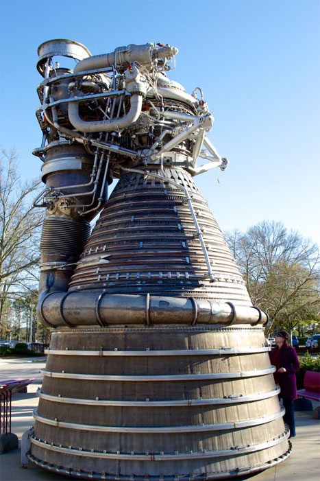
An F-1 engine on display at NASA's Marshall Space Flight Center
.
Enter our young rocket scientists
Tom Williams is the kind of boss you want to have. He's smart, of course—that's a prerequisite for his job as the director of the NASA Marshall Space Flight Center's (MSFC) Propulsion Systems Department. But he doesn't mind stepping back and giving his team interesting challenges and then turning them loose to work out the details. Case in point: NASA's Space Launch System (SLS), intended to be an enormous heavy-lift system that will rival the Saturn V in size and capabilities. In thinking about propulsion for the SLS, NASA for the first time in thirty years is considering something other than solid rocket boosters.
The decision to use a pair of solid rocket boosters for the Space Shuttle instead of liquid-fueled engines like the F-1 had been partly technical and partly political. Solid fuels are hugely energy dense and provide an excellent kick to get a spacecraft moving off of the ground; also, selecting solid fuel boosters allowed the government to send some available contracting dollars to companies involved with building intercontinental ballistic missiles, leveraging that expertise and providing those companies with additional work.
But solid boosters have several downsides, including an inability to stop combustion. Without pumps to switch off or valves to close, solid boosters work a lot like the "morning glory" sparklers my dad used to buy on the Fourth of July—once lit, they burn until they're done. Solid rocket booster design decisions, specifically in regard to containing combustion, contributed to the destruction of the Space Shuttle Challenger and the death of its crew (though Challenger's destruction was more a failure of NASA management than of technology).
Still, as the Space Shuttle program drew to a close and potential successors came and went, the inertia of solid boosters and the facilities and people that produced them ensured that they remained a part of the plans.
SLS gave NASA the chance to do a total rethink. As design studies got underway, Williams realized it might be a good idea to re-familiarize the MSFC Propulsion Systems Department with huge kerosene gas generator engines like the F-1 (referred to in shorthand as "LOX/RP-1" or just "LOX/RP" engines, after their oxidizer and fuel mixture of liquid oxygen and RP-1 kerosene). Scale aside, the F-1 is conceptually a relatively simple design, and that simplicity could translate into cost reduction. Reducing cost for space access is a key priority—perhaps even the overriding priority—outside of safety.
There was a problem, though. SLS' design parameters called for a Saturn V-scale vehicle, capable of lifting 150 metric tons into low Earth orbit. No one working at MSFC had any real experience with gigantic LOX/RP-1 engines; nothing in the world-wide inventory of launch vehicles still operates at that scale today. So how do you make yourself an expert in tech no one fully understands?
Nick Case and Erin Betts, two liquid engine systems engineers working for Williams, found a way. Although no launch vehicles that used F-1 engines are still around, actual F-1s do exist. Fifteen examples sit attached to the three Saturn V stacks on display at NASA facilities, including MSFC; dozens more are scattered around the country on display or in storage. Williams' team inspected the available engines and soon found their target: a flight-ready F-1 which had been swapped out from the launch vehicle destined for the to-be-canceled Apollo 19 mission and instead held in storage for decades. It was in excellent condition.
Case and Betts spearheaded the paperwork-intensive effort to requisition the F-1 from storage and get it into their workshop. They were aided by R.H. Coates, a more senior member of Williams' team and lead propulsion engineer for the SLS Advanced Development Office. Williams offered encouragement and assistance from the management side, but the team was otherwise given free rein on how to proceed. After some study, they came to Williams with a request that was pure engineer: "Why don't we just go ahead and take this thing apart and see what makes it work?"
Williams said yes. "It allowed some of our young engineers to get some hands-on experience with the hardware," he told me, "what we would term the 'dirty hands' approach to learning, just like you did when you took apart your bicycle when you were a kid, or your dad's lawnmower or his radio. One of the best ways to learn as an engineer, or in anything, is to take it apart, study it, ask questions."
And then, hopefully, build a better one.
The plans! The plans!
The F-1 teardown started in relatively low-key fashion. As the team dug into the engine, it became obvious that the internal components were in good shape. In fact, though there was some evidence of rainwater damage, the engine overall was in great shape.
The team initially wanted to build an accurate computer model of every component in the engine so that its behavior could be modeled and simulated, but another goal soon began to take shape: maybe, just maybe, they could mount some of the engine components on a test stand and make the F-1 speak again after 40 years.
Why was NASA working with ancient engines instead of building a new F-1 or a full Saturn V? One urban legend holds that key "plans" or "blueprints" were disposed of long ago through carelessness or bureaucratic oversight. Nothing could be further from the truth; every scrap of documentation produced during Project Apollo, including the design documents for the Saturn V and the F-1 engines, remains on file. If re-creating the F-1 engine were simply a matter of cribbing from some 1960s blueprints, NASA would have already done so.
A typical design document for something like the F-1, though, was produced under intense deadline pressure and lacked even the barest forms of computerized design aids. Such a document simply cannot tell the entire story of the hardware. Each F-1 engine was uniquely built by hand, and each has its own undocumented quirks. In addition, the design process used in the 1960s was necessarily iterative: engineers would design a component, fabricate it, test it, and see how it performed. Then they would modify the design, build the new version, and test it again. This would continue until the design was "good enough."
Further, although the principles behind the F-1 are well known, some aspects of its operation simply weren't fully understood at the time. The thrust instability problem is a perfect example. As the F-1 was being built, early examples tended to explode on the test stand. Repeated testing revealed that the problem was caused by the burning plume of propellent rotating as it combusted in the nozzle. These rotations would increase in speed until they were happening thousands of times per second, causing violent oscillations in the thrust that eventually blew the engine apart. The problem could have derailed the Saturn program and jeopardized President Kennedy's Moon landing deadline, but engineers eventually used a set of stubby barriers (baffles) sticking up from the big hole-riddled plate that sprayed fuel and liquid oxygen into the combustion chamber (the "injector plate"). These baffles damped down the oscillation to acceptable levels, but no one knew if the exact layout was optimal.
.
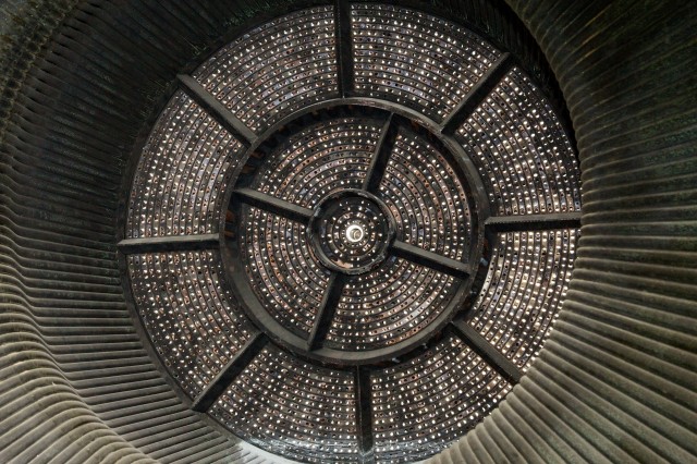
Detail on an F-1 engine injector plate at the forward end of the nozzle. Fuel and liquid oxygen are sprayed out of these holes under tremendous pressure, with each ring alternating propellant and oxidizer.
.
The baffle arrangement "was just a trial and error thing," explained Senior Propulsion Engineer R.H. Coates. "But we'd like to model that and say, well, what if you took one of those baffles out?" Because the baffles are mounted directly to the injector plate, they take up surface area that would otherwise be occupied by more injector holes spraying more fuel and oxidizer; therefore, they rob the engine of power. "So if you want to up the performance on this thing, we can evaluate that with modern analytical techniques and see what that does to your combustion stability."
But before any "hot-fire" testing could occur, the team had to take the very physically real F-1 engine and somehow model it. It's easy—well, relatively easy—to turn a set of CAD files into a real product. Turning a real product into a set of CAD files, though, requires a bit of ingenuity, especially when that product is a gigantic rocket engine.
To tackle the task, NASA brought in a company called Shape Fidelity, which specializes in a technique called "structured light scanning." If you don't have access to the laser from TRON, structured light scanning is just about the next best way to cram something inside of a computer.
.
Firing my laser
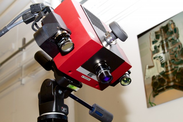
The structured light scanner assembly. The middle lens is the projector, and the outer two lenses are cameras that look at how the projector's light falls onto the surface being scanned.
.
The exterior of the F-1 was meticulously photographed and then mapped with a structured light scanning rig, which uses a projector to paint a pattern of stripes onto the surface being scanned. Mounted on the side of the projector are two cameras which each record how the pattern falls on the surface being scanned. For every exposure, the projectors and camera capture sixteen different stripe patterns.
The structured light rig can focus on an area ranging from 65mm in size all the way out to 1.5 meters, so getting a surface scan of the entire F-1 engine required a lot of crawling around and manually aiming the scanner rig. It wasn't immediately obvious how a bunch of handheld scan images could maintain coherency—how do you indicate to the scanner that picture 2 is linked to picture 1?
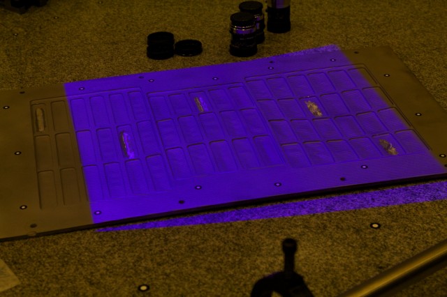
Scanning a small object with the structured light scanner. The alternating horizontal bars in the purple projection are used by the cameras to detect surface detail. Note positional decals around the object's perimeter.
.
The answer was both simple and brilliant. "You notice these little targets? These little stickers?" said Shape Fidelity engineer Rob Black, who was demonstrating the equipment for me. Black indicated the small white-on-black circular dots pasted on the test material on the table in front of us. All around us were disassembled F-1 engine pieces, and I noticed that every single component was peppered with the little dots. "We stick these things on by hand, and the scanner sees these targets, so when we move from one position to the next, it can see what's coming... and stitch everything together. That way, we don't have to use encoders or robots."
Each part gets tiny dots hand-applied in what is effectively a random, unique pattern. The structured light software can use the unique layout of dots to stitch together all pictures of the object being scanned, without requiring the camera to be mounted in a motion controlled rig.
"We took just a regular digital camera and walked around the engine and took photographs," Black said. "The software took all those photographs and built a 3D coordinate for each of the targets, and what you get is a very sparse data set—it's basically the X-Y-Z value of the center of these points."
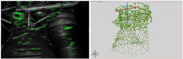
The rough point-cloud assembled by the structured light scanning application, using the black and white positional dot stickers.
.
After the point map was assembled, Black performed a detailed structured light scan of the entire outside surface of the engine. "But what we wanted was a scan of the inside—the vanes, the clearances, all the definition of the interior," explained Black.
Taking the F-1 apart to get at its insides was always part of the plan, but as the team proceeded, it became obvious that actually cracking the thing open without breaking it was going to require specialized tooling—tooling that might have existed 40 years ago but which has long since been destroyed or lost.
The exterior scan was therefore used to develop the specialized tooling needed to fit the F-1's nuts, bolts, and fasteners. Some of the bolts were annoyingly unique—Betts noted that at least one high-torque bolt in the turbopump assembly required its own special torque adapter to remove.
.
Weiter geht es hier: http://arstechnica.com/science/2013/04/how-nasa-brought-the-monstrous-f-1-moon-rocket-back-to-life/
6537 Views