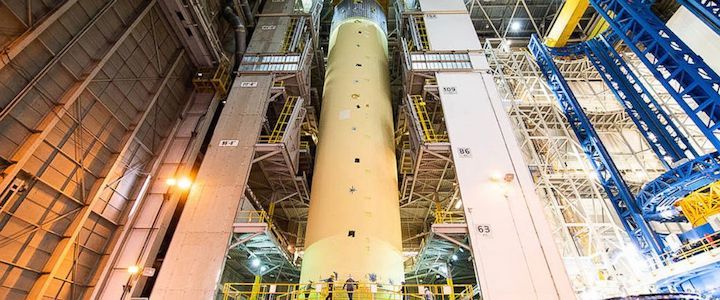
NASA moves liquid hydrogen tank to Huntsville for testing
This Nov. 26, 2018 photo released by NASA, shows the 149-foot long tank which is part of the Space Launch System in Florida. NASA is moving a massive liquid hydrogen tank to Huntsville, Ala., for testing as part of its plans to eventually return to the moon.
NASA is moving a massive liquid hydrogen tank to Huntsville, Alabama, for testing as part of its plans to eventually return to the moon.
The 149-foot-long tank is part of the Space Launch System.
The version moved Friday from NASA's Michoud Assembly Facility in New Orleans is a test model, meaning it won't actually be launched into space.
It was moved — slowly and horizontally on its side — out of the factory where it was constructed to a barge called the Pegasus. From there it will travel up river to the Marshall Space Flight Center in Huntsville, where it will undergo strenuous testing designed to mimic the conditions of traveling into space.
The testing is intended to make sure that the tank design can withstand the worst-case conditions, said Sam Stephens, test manager for the Space Launch System's core stage. NASA also runs computer models to simulate all the conditions the tank might encounter, Stephens said.
"We will test it until it fails, until it cracks," said Stephens. "We are going to subject it to stuff we never want the flight vehicle to see."
The tank weighs more than 100,000 pounds, said Stephens.
"It's a pretty good size. It is the biggest tank we've ever built and it's going to go on the largest launch vehicle we've ever built," he said, referring to the U.S.
The tank holds 537,000 gallons of liquid hydrogen that along with liquid oxygen will help propel the rocket and its cargo into space.
The information learned from the testing will help scientists as they're building future tanks for the Space Launch System.
Quelle: abcNews
+++
“Plan D for Outer Space” — NASA updates EM-2 mission baseline
Coming off this year’s manifest changes to the early missions in NASA’s Exploration campaign, the outline and major parameters for the first crewed Orion flight were formally updated to reflect those big picture updates. Exploration Mission-2 is still a test flight to check out Orion with crew system upgrades and circumnavigate the Moon, but the early part of the mission was reworked to take into account the change in configuration of the Space Launch System (SLS) launch vehicle.
The SLS Boosters and Core Stage will leave its upper stage with Orion attached in a higher insertion orbit on EM-2. After a revised post-insertion sequence, the upper stage will take Orion and crew to an even higher and more elliptical orbit than earlier plans. Following separation from the upper stage, Orion will spend almost a day longer in Earth orbit than previously planned at the start of the mission before leaving Earth for a Lunar flyby.
Transferring higher SLS performance to higher MECO orbit, ICPS
The Exploration Mission-2 (EM-2) mission has always been the first Orion crewed flight, but the mission profile has gone through multiple revisions over the years, from a high-lunar orbit mission to a cislunar rendezvous with an asteroid redirect spacecraft to the current “hybrid triple” outline. Even within that outline, the upper stage for the mission has gone back and forth between the Delta upper stage derivative Interim Cryogenic Propulsion Stage (ICPS) and the Exploration Upper Stage (EUS) that is still in development.
With early SLS launches moving back to the Block 1 vehicle configuration, the mission baseline was formally revised recently. “It was an update to switch from the EUS to ICPS, so in that switch because of the performance differences in the stages we had to re-optimize part of the mission around the ICPS,” Nujoud Merancy, NASA Exploration Mission Analysis Lead, explained.
“So this is the updated baseline for EM-2.”
In terms of launch and insertion, the first few minutes of EM-2 will look similar to the first SLS launch on the Exploration Mission-1 (EM-1) test flight of an uncrewed Orion spacecraft; however, in switching back to the Block 1 ICPS the new EM-2 baseline also changes some significant mission parameters from EM-1. The first change is to raise the high-end of the insertion orbit from 975 nautical miles to 1200.
In its Block 1 configuration the SLS Boosters and Core Stage will take a little over eight minutes to deliver the fully-loaded ICPS and its crewed Orion payload to an insertion orbit that is just below the velocity needed to stay in Earth orbit; this allows the empty Core Stage to safely breakup away from land and populated areas when it reenters the atmosphere.
Revised Exploration Mission-2 (EM-2) outline, as presented by NASA officials to the NASA Advisory Council (NAC) Human Exploration and Operations (HEO) Committee in early December. Credit: NASA.
“We had performance on the Core Stage, so did we want to raise the insertion off the Core to push that performance uphill,” Merancy said explaining the trade-off. “We did end up taking that option, it was a trade between a 975 nautical mile drop off — it drops off lower than that but the coasting apogee would be 975 — but we raised that up to 1200.”
“We have that performance in the Core Stage on EM-1 as well, but being the first flight and we didn’t need to push it uphill, we opted to keep that performance on the Core Stage for the first flight and it increases your engine-out capability on SLS,” she elaborated.
“For EM-2, the first stage would have been flown and because the ICPS and the in-space portion is more the performance driver, we’re opting to raise that Core Stage insertion so we can have more margin on ICPS, which gives us more launch opportunities for ICPS.”
Increasing the apogee of the vehicle at Core Stage Main Engine Cut Off (MECO) also provides some improvement to the overall period of days each month where Orion can reach the Moon on SLS.
“The elliptical parking orbit limits your launch opportunities in the month because you can only go when the Moon is in the direction of the apogee, so pushing performance on the ICPS increases the number of days,” she said. “I think basically we’re between eight to ten days with the difference pushing that uphill.”
First upper stage burn moved up
The second change reorders the sequence of post-insertion events after Orion and ICPS have separated from the Core Stage following MECO. Both the Orion/ICPS mated combo and the Core Stage are still in an orbit with a perigee or low point of around 20 nautical miles that the ICPS must raise to a higher altitude to stay in orbit.
On EM-1, the Perigee Raise Maneuver (PRM) is performed by ICPS when the vehicle reaches the apogee of the insertion orbit, about 40 minutes after liftoff and over thirty minutes after MECO, raising the perigee to 100 nautical miles. For EM-2, the PRM burn was moved up in front of Orion’s solar array deployment with ignition ten minutes after MECO, in part to provide a bigger window of time in between major ICPS burns for initial Orion checkouts.
“The apogee on EM-1 had been picked [for PRM] to maximize performance, but that puts it in sort of an awkward position for Orion because the solar array deploy occurs between MECO and PRM and then you have to park them for PRM and then you coast again,” Merancy explained. “So we really wanted to look at whether we could move that PRM earlier.”
SLS Block 1 Crew vehicle configuration. The EM-2 mission baseline has formally moved back from Block 1B Crew to Block 1 Crew, which will be used for both EM-1 and EM-2. Credit: NASA.
The PRM burn on EM-2 will raise the perigee and apogee to an orbit of 100 nautical miles by around 1450 nautical miles. Performing it earlier provides more time for Orion’s solar array deploy and initial spacecraft checkouts between the two major ICPS burns with Orion. The resultant orbit also has a slightly longer period, which provides a little more time before the Apogee Raise Burn (ARB) that ICPS does at the end of the first orbit when the vehicle is at the 100 nautical mile perigee.
“It de-optimizes the PRM so there’s a little bit of a performance hit, but it’s a much more I’ll say stable period then for Orion to deploy the solar arrays after PRM and perform checkout in a quiescent, coasting LEO (Low Earth Orbit). So it’s really an operational consideration to move it forward to make the rest of the Orion checkout more ops-friendly.”
The EM-2 mission profile now also baselines a single low-altitude Earth Orbit, which reduces MMOD risk. In the prior baseline when Orion was flying with EUS, it stayed in the low-altitude “parking” orbit for two revolutions; in that case, Orion and EUS were flying in a circular orbit around 100 nautical miles, which is largely below the altitudes with high MMOD risk.
“The MMOD environment starts at around 500 nautical miles from those satellite breakups that occurred,” Merancy explained. “When we were staging on EUS we can do a couple of orbits and there’s no real difference in MMOD risk; however with ICPS and the elliptical orbit, once the apogee gets above 500 nautical miles you have MMOD concerns.”
“So the other advantage to the early PRM is it boosts up that apogee, we have a slightly longer orbit,” she added. “We went through the whole thing with flight ops (operations), they went through and made sure they could finish Orion checkout, and so we are opting for the first rev (revolution) to reduce MMOD risk but there’s still sufficient time to perform the checkout needed prior to TLI, or in this case ARB.”
ICPS will do a full TLI burn with the uncrewed Orion on EM-1; for the first crewed Orion on EM-2, ICPS it will do an Apogee Raise Burn that takes Orion to the second orbit of the hybrid triple. The profile has Orion flying in three orbits: a low Earth orbit still attached to the booster upper stage, a high Earth orbit (HEO) by itself that was going to last for about one day, and a single solo lap around the Moon before returning to splashdown on Earth. NASA has been considering variations of this mission for EM-2 going back several years.
“The ICPS is capable of doing the full TLI burn, we’re only utilizing part of it,” Merancy said. “Both are well within what ICPS can do, that’s what it’s doing on EM-1.”
Increasing High Earth Orbit altitude and duration
The third change uses the ARB to burn to an even higher apogee than previous planned, increasing the duration of the High Earth Orbit from 24 hours to 42 hours by almost doubling an already very high apogee. “The HEO is around 205 by 59260 nautical miles,” Merancy noted.
“They’ll have a really good view from the HEO and then they get to go by the Moon,” she said of the future EM-2 crew.
The long orbit allows an extended evaluation of the performance of new spacecraft systems close to home, especially the crew systems that will be making their first flight. “The whole point of the HEO is to provide a checkout near the Earth where you don’t need big burns to come home, we’re one to two days from home,” Merancy said.
The Environmental Control and Life Support System (ECLSS), crew displays, and other crew systems will be making their debut in Orion on EM-2.
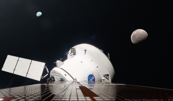
Orion will still do a Trans-Lunar Injection (TLI) burn on its own that provides the remaining change in velocity or delta-V needed to go from the HEO to a Lunar flyby, but the bigger ARB burn by the ICPS at the end of the first orbit reduces the delta-V for Orion’s TLI. “Raising the apogee [means] less demands on Orion’s prop (propellant) system for the upcoming TLI, which leaves more performance should you need an abort post-TLI.”
ICPS fires for a second time to carry Orion away from Earth. On EM-2, Orion’s solar arrays will be deployed between the first two upper stage burns. Credit: Nathan Koga for NSF/L2.
“It’s about a thousand pounds of Orion prop,” Merancy said about the difference in orbits. “So there is an advantage to having that be a bigger orbit, in that then Orion has more prop available post-TLI should other emergencies occur.”
It would have been theoretically possible to pick an orbit with a period between 24 and 42 hours, but practically Merancy said they would not do the TLI burn in the middle of the crew’s sleep period. “We could have gone up to around 27 hours and then you can’t do the orbit period because TLI would have been in crew sleep. Forty-two hours was sort of the next morning for the crew day.”
The Orion TLI burn would be at perigee of the HEO, which would be at the end of that orbit’s period.
“So there is a method to the madness there,” she added. “We got to 42 hours so we can align TLI with the crew being awake and it’s performance that ICPS can get to and leaves more prop on Orion, so all of those factors sort of optimized that orbit period.”
“And we found that the aborts from the HEO were roughly equivalent between the 24 and 42 [hour orbits], so there wasn’t a reason to stay in the 24, comparatively.”
Circumlunar timeline mostly unchanged
After the Orion TLI burn, the rest of the EM-2 mission remains as previously baselined, with the round trip to the Moon taking four days out and four days back. “The Orion in-space portion of the mission looks roughly the same as before, it’s just the HEO that’s different,” Merancy said.“So the TLI, the Lunar flyby, Orion is targeting the same as it was before, it’s just added hours in HEO before it goes there. So it was a nine-day mission before, now it’s a ten-day mission.”
Orion and crew will swing around the Moon at an altitude of about 4800 nautical miles.
Revisiting cubesats
After dropping Orion off in its high, elliptical Earth orbit early on the first day of the mission, ICPS will make its own TLI burn using its flyby of the Moon to head into a heliocentric disposal orbit. “I think we’re in the like 20 to 30 minute range, but Orion will do the separation, do a burn to gather distance from ICPS, and then ICPS will do a disposal burn,” Merancy explained.
“We still baselined a heliocentric disposal for ICPS, so it essentially completes TLI after Orion is separated and will continue on to its disposal. It just has to wait enough time for Orion get safe separation.”
Although the major outlines of the mission are now rebaselined, it will continue to be iteratively refined with subsequent changes generally of smaller degrees. One of the things that will be looked at now is whether there is any secondary payload capability.
Orion Stage Adapter for EM-1 in the Space Station Processing Facility following arrival at Kennedy Space Center in April. The cubesat dispensers can be seen around the top circumference. Following the rebaselining of the basics of the EM-2 mission, NASA will re-examine whether secondary payloads like this can be accommodated. Credit: NASA/Glenn Benson.
On EM-1 thirteen cubesats are being flown in an adapter that sits on top of the ICPS; they will be deployed from ICPS after Orion has separated from the upper stage. Merancy said they set aside some of these questions while focusing on baselining the mission for its main objectives.
“When we were trying to baseline it we just sort of ground ruled out a lot of those secondary questions, so the baseline doesn’t show cubesats,” she said. “That is another item we’re working now — do we want to now basically add cubesats or use performance in other ways.”
“It’s sort of an iterative process, we’ve figured out that much and now we’re going to look to see do we want to add cubesats or not. We’re working with the Science office and SLS on that question, actually.”
Quelle: NS
---
Update: 16.01.2019
.
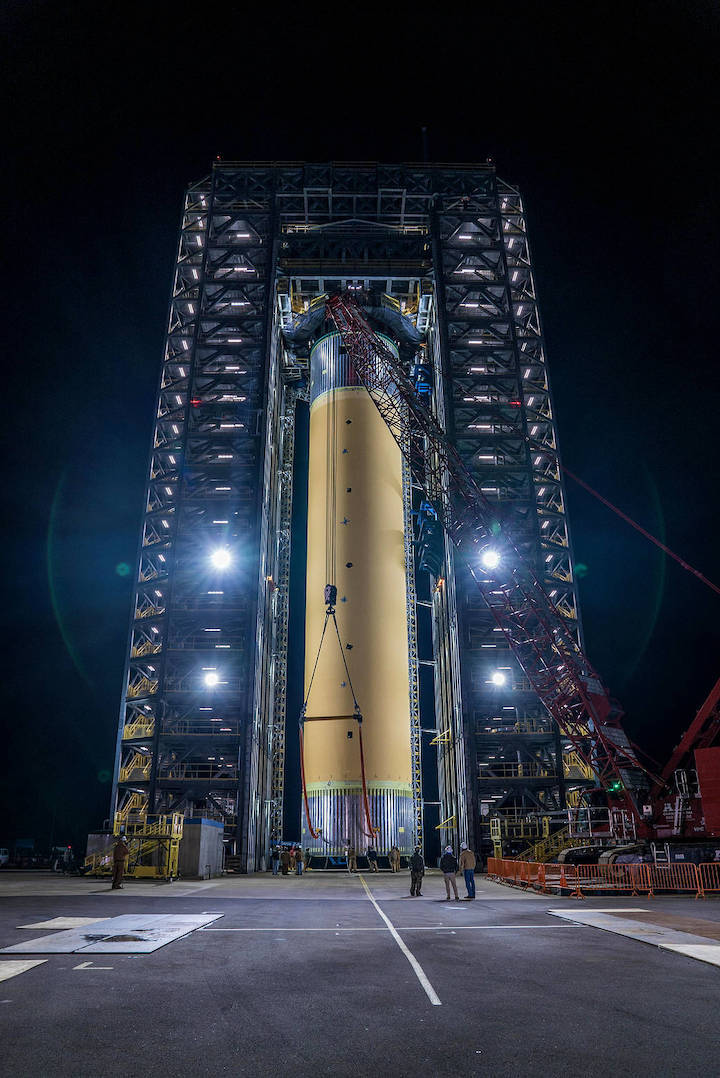
SLS Liquid Hydrogen Tank Test Article Loaded into Test Stand
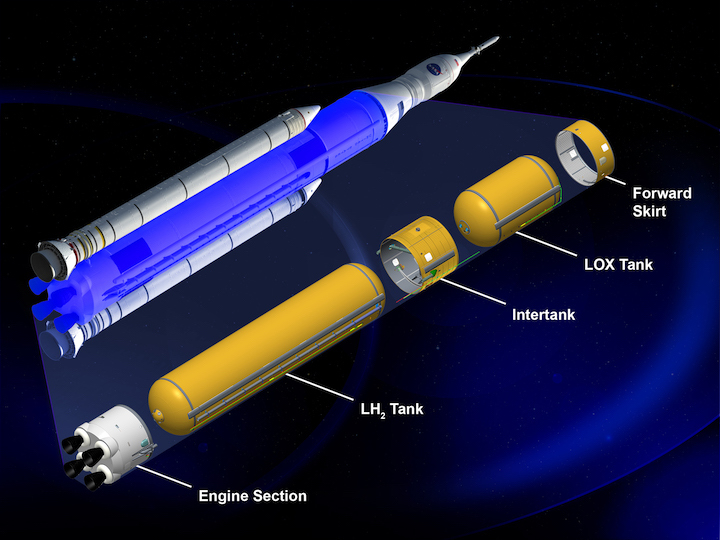
The largest piece of structural test hardware for America’s new deep space rocket, the Space Launch System, was loaded into Test Stand 4693 at NASA’s Marshall Space Flight Center in Huntsville, Alabama Jan. 14, 2019. The liquid hydrogen tank is part of the rocket’s core stage that is more than 200 feet tall with a diameter of 27.6 feet, and stores cryogenic liquid hydrogen and liquid oxygen that will feed the vehicle’s RS-25 engines. The liquid hydrogen tank test article is structurally identical to the flight version of the tank that will comprise two-thirds of the core stage and hold 537,000 gallons of supercooled liquid hydrogen at minus 423 degrees Fahrenheit. Dozens of hydraulic cylinders in the 215-foot-tall test stand will push and pull the tank, subjecting it to the same stresses and loads it will endure during liftoff and flight.
Image Credit: NASA/Tyler Martin
Quelle: NASA
----
Update: 29.01.2019
.
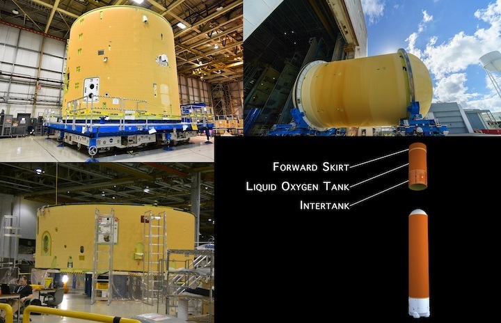
Boeing starts final assembly for NASA’s first SLS Core Stage, work picks up for the second
Over the past month Boeing assembled the top half of the first Space Launch System (SLS) Core Stage in a vertical stacking cell at the Michoud Assembly Facility (MAF) in New Orleans. The intertank, liquid oxygen (LOX) tank, and forward skirt were bolted together as the major part of the so-called “forward join” of the new rocket stage.
Final assembly of the stage involves first connecting its major elements into a top and bottom half before a final connection takes it out to over two-hundred feet in length with its engines installed. Once the Boeing production team at MAF finishes installation of remaining plumbing and wiring in the engine section, it will head into the other stacking cell at MAF to start assembly of the aft join.
As the first stage comes together, major construction of the second Core Stage is now beginning with propellant tank welding set to begin shortly.
Top half of the rocket assembled
“Forward join is structurally complete,” John Shannon, Boeing’s Vice President and Program Manager for SLS, said in a January 23 interview. Boeing is the prime contractor for the Core Stage.
“The LOX tank is sitting on top of the intertank and all of the bolts running around the flange have been torqued. The forward skirt is sitting on top of the LOX tank and we’re about two-thirds of the way through the final torques for the forward skirt.”
The three forward join elements have flanges at both ends where structural rings are integrated into the structure and provide a mating surface to join each pair of elements.
“The team is working on the wire harnesses that run between the different elements and that will go through the systems tunnel,” Shannon added. “It’s an awe-inspiring sight. It’s really gratifying to see it all come together.”
SLS Core Stage production was one of the activities that were allowed to continue while NASA was essentially closed for five weeks by the partial U.S. government shutdown. Completing assembly of the first Core Stage, Core Stage-1 (CS-1), is a critical path in the assembly, integration, and test schedule to reach the launch of Exploration Mission-1 (EM-1).
EM-1 is a test flight incorporating the first SLS launch, integration of SLS with NASA human exploration Orion spacecraft, and Orion’s first solo flight that is planned to spend several days in lunar orbit before returning to Earth.
Just as NASA funding ran out right before Christmas, the Boeing production team at MAF completed standalone work on the trailing piece of the forward join, the LOX tank. Assembly and integration of the forward skirt for CS-1 was completed in July and standalone work on the intertank was completed in early October.
Stacking work is done in Cell A and Cell D in the Vertical Assembly Building (VAB) at MAF, Building 110. The intertank was shuffled in and out of the renovated Cell D in the Fall; final prep work on the LOX tank delayed the forward join, and Boeing and NASA took the opportunity to stack the LH2 structural test article (STA) from late October through early December.
By the time the LH2 STA rolled out of the VAB at Michoud on December 14 for a barge trip up to the Marshall Space Flight Center in Alabama, the intertank was set up back in Cell D and ready for stacking. Over the holidays, the LOX tank was moved into the VAB at MAF, lifted up into Cell D and put on top of the intertank, so the two pieces could be bolted together.
Three-hundred and sixty bolts at one-degree intervals around the circumference hold each flange together. The bottom flange of the LOX tank was bolted to the top one on the intertank.
“We retired an enormous amount of program risk when we put [them together],” Shannon explained. “This is the first time we’ve stacked real flight elements to real flight elements and you know we’ve done white light scans and 3-D CAD (Computer Aided Design) characterization and we measured it like crazy and when we put the LOX tank on the intertank it fit perfectly, there were just no issues at all.”
“The same with the forward skirt, it was just as slick an operation as you could possibly imagine,” he added. With the three elements mated structurally and wiring connections being attached, the next major step in the forward join is to install the top part of the LOX feedlines that will deliver the oxidizer from the top of the stage to the engines at the bottom.
“We mount two very large S-ducts coming out of the bottom of that LOX tank and then they’ll exit through the intertank to form the very upper part of the downcomers that bring the liquid oxygen down to [the] engine section,” Shannon explained. He said the team was planning to start the installation over this past weekend or early this week.
Left open for mating, the areas around each of the completed flanges will soon be sprayed with spray-on foam insulation (SOFI) to provide thermal protection. The foam “closeouts” of the bolted flanges will be manually sprayed by technicians while the top part of the stage remains in Cell D.
Shannon said there were some other small work items also left to do there: “It’s just a bunch of work for systems tunnel and brackets for the feedlines and it’s just a bunch of small work. We’re doing some DFI work in there, as well.”
Even without its engines installed, an assembled Core Stage is too long to stack vertically in one place at MAF, so they will be vertically assembled into two half-stages first before the whole stage is finally connected while horizontal in the nearby Final Assembly area of Building 103.
Engine section integration wave rolls into aft join work
The pacing item in overall assembly, integration, and testing for CS-1 is the engine section. The element at the bottom of the stage which has more of everything and most of its moving parts has taken the longest to complete, but Shannon said they’re continuing to get closer to that milestone.
“We’re doing really well on that, working through our final wire harness installations and checkouts,” Shannon said. “The engine section has more wiring and instrumentation in it than any other element so we’re taking advantages of the lessons we learned in doing the forward skirt and the intertank.”
“Tubing is just about completed in it,” he added. “As far as major structure left the four LH2 feedlines that go to the engines are left to be installed.”
Core Stage-1 engine section in its integration area at MAF in August, 2018. An environmentally-controlled work area will be maintained on the inside of the element until its integration is complete. Credit: Philip Sloss for NSF/L2.
“They’re staged outside of the engine section. We don’t want to put those in [yet] because they take up so much space until we finish up the wiring and the tubing. Once that’s complete we’ll be able to put those LH2 lines in.”
The bulk of the remaining work is getting all the wiring harnesses in position and making sure they weren’t damaged going in. “For all the wiring, we’ve done our installations on 105 of 153 of them, for the big wire harnesses,” Shannon noted.
“Those 153 wire harnesses require 5,113 clamps and we’ve installed 4,801 of them, so you can see we’re getting very close to the end of all of that.” Once the wiring runs are clamped into position, they are tested to make sure they’re healthy after install.
“It’s your standard continuity/high-potential checks, where you’re checking insulation and you’re checking copper path,” Shannon explained. “You’re making sure that as you put wire into these clamps that you didn’t do any damage to the wire, so it’s basically just a functional check of the health of the wire harness itself.”
Core Stage-1 will be outfitted with a significant amount of development flight instrumentation (DFI) and Shannon said that is now being patched into the already-tested engine section wiring. “The way it works is you run the wiring, you do the continuity and high-potential checks, and then you splice in those accelerometers or temperature transducers or whatever it might be into that wiring harness,” he explained.
“There’s a grand total of about 500 splices that have to be done for that development flight instrumentation and we’re probably about 150 into that splicing, so a lot of wire activity is going on, very fine, detailed work that we have to do to finish out that element.”
Once all the wiring work is complete, the avionics boxes will be installed in the engine section; 3-D printed shells that mimic their form and fit and are currently holding their place on the avionics shelf and other locations inside. “We want to finish up the wiring and then the last step is we’ll mount the avionics boxes in and then do the final mate of those wiring harnesses to those avionics boxes,” Shannon noted.
Shannon said the liquid oxygen propellant lines are essentially all installed. “It’s the downcomer coming down the side and going into the engine section and there’s a Y-duct to split the flow from each of the two downcomers, since we have four engines. Then at the end of that Y-duct split is a prevalve, just like we had on the Space Shuttle, and then going down from that prevalve is the LOX feedline to each engine and that’s completed on both sides.”
“There’s a crossover duct which runs almost the semicircle halfway around the engine section that equalizes the pressure between those two Y-ducts and we had one section out of that so that we could get to the final tubing and wiring,” he added. “It’s already been checked in there and fits fine, so it’ll be a simple operation. It’ll be just whenever we finish the wiring and tubing.”
The bottom end of a replica of the Core Stage LOX feed system used for anti-geyser testing at the Marshall Space Flight Center in 2014-2015, showing the semi-circular crossover line that runs between the two LOX feedlines that enter the engine section. One section of the flight crossover line is the only remaining part of the LOX system to install. Credit: NASA.
Completion of engine section integration will be a big milestone, but it also leads straight into the aft join sequence to assemble the bottom half of the rocket.
“It is kind of a rolling wave of work, because once the engine section work is done, then we integrate with the boattail and there’s a lot of the wires and tubes that go across the interface between the engine section and the boattail,” Shannon said. “We’ll take it over to Cell A to integrate it with the boattail, and that’ll be a couple months of doing not just the structural mate, but the tubes and running the wires and getting that all squared away with the TPS (Thermal Protection System) as well.”
“Then we’ll bring the LH2 tank in and mate it with that stack, engine section-boattail in Cell A.”
Aft join sequence into Cell A
The boattail is in part a heatshield at the base of the stage and an extension on the bottom of the engine section. “It is ready and waiting,” Shannon noted.
“On the engine section we’re also doing a lot of work on the outside. They’ve started putting up the white Hypalon paint over the cork and they’ll do some of that work on the boattail as well, but otherwise the boattail is ready to go. But if you looked at it you’d see a lot of coiled wires ready to run up into the engine section after we do the mate.”
A graphic of the base of the SLS vehicle showing the location of different elements; the boattail (BT) assembly for the Core Stage includes that and the base heatshield (BHS). Engine-mounted heatshields (EMHS) are thermal blankets that will attach to the boattail and clips at the base of each RS-25 engine nozzle. Credit: NASA.
Once the boattail is physically mated to the bottom of the engine section and all of the tube and wiring connections are finished, functional testing of the engine section systems will begin. “When we get into the Cell A functional testing, which will take about thirty days, we’re actually sending signals down wires, receiving them in avionics boxes, checking output, checking calibration curves, all those types of things,” he said.
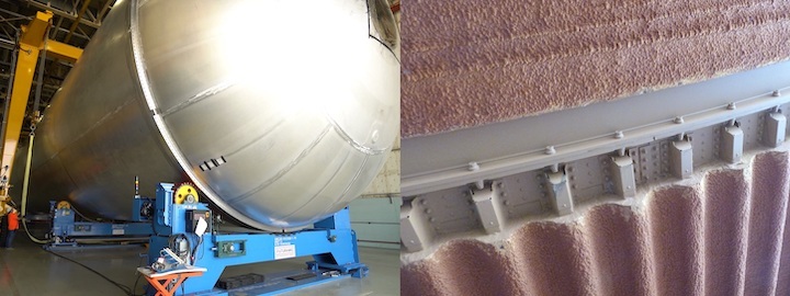
The LH2 tank for Core Stage-1 is almost complete, with one remaining installation to do. “The aft manifold is like this bubble that has the four lines that come out of it to the four hydrogen feed lines,” Shannon explained.
“That aft manifold has been outfitted with the anti-vortex baffles, so it’s been all built up. At noon today it should go over to that controlled work access area from its clean room area and we’ll plan on installing that aft manifold probably tomorrow late,” he said at the time of the interview on January 23.
Core Stage LH2 qualification tank in the Final Assembly area at MAF in August, 2018. The flight tank for Core Stage-1 currently takes up the same position after the qual tank was shipped to Marshall as the centerpiece of the structural test article (STA). The work stand in the foreground of the image encloses the forward end of the qual tank; for the flight tank, work on the forward end is complete and the stand has been moved to the aft end for installation of the aft manifold. Credit: Philip Sloss for NSF/L2.
The work flow for this first Core Stage build has been regularly adjusted to try to juggle blocks of work, Tetris-style, into different blocks of time. With additional time before the LH2 tank would be mated to the engine section, Boeing and NASA moved forward one of the final assembly jobs, installation of the LOX downcomers on opposite sides of the tank.
“We did some get ahead work — we realized it would be easier to put on the brackets for the downcomers, so we put on forty-four of these big aluminum brackets that run down the side of the LH2 tank that will support each of the downcomers and that work all went extremely well, also,” Shannon noted.
After the tank is stacked vertically with the engine section in Cell A, the sections of the two LOX downcomers will be attached both to the outside of the tank and joined to the sections already installed on the engine section.
Shannon said the get-ahead work on the brackets is almost complete: “We’ll do some finish-out TPS work over the next couple of weeks and then be ready to meet the engine section in Cell A.”
Shannon also noted that a lot of foam closeouts on both the LOX and LH2 tanks and other parts of the stage were recently completed: “We really had a push over the last two months for both the pour TPS and the spray TPS and we formed a special team under a guy named Tim Burroughs.”
“They did a great job over the holidays as well in doing the TPS closeouts and the inner and the outer pours on the engine section, so we’ve made a lot of progress on the TPS over the last two months.”
Core Stage-2 structures being assembled
In parallel with final assembly of Core Stage-1, the pace of work is increasing for Core Stage-2 (CS-2). “When you’re doing the first part of Core Stage-2, it’s structural elements and welding,” Shannon said. “When you’re doing final assembly, it’s a lot of TPS and wiring and checkouts so we’re effectively able to divide the workforce for that phase of the vehicle that is being completed at that time.”
Four out of the five major elements are welded structures. For CS-2, the aluminum alloy panels for the liquid oxygen tank, the forward skirt, and the engine section have already been assembled into barrels and domes, which then go into the Vertical Assembly Center (VAC) that is also located in the VAB, Building 110.
The Core Stage-2 forward skirt barrel in storage at MAF in August, 2018. The two L-rings that complete the primary structure have already been welded and are now being coated with corrosion-protecting primer along with the bare metal areas seen here between barrel panels. Credit: Philip Sloss for NSF/L2.
“We’ll get into the welding of the LOX tank next week, they were moving the dome over yesterday when I was in that aisleway in the way,” he said.
The LOX tank parts follow the CS-2 forward skirt into the VAC; welding of two rings to the top and bottom of the forward skirt was completed at the end of 2018. “We finished the welding of the flanges on the forward skirt for Core Stage-2 and it’s in priming now over in Cell G,” he noted.
The LH2 tank will be the final structure that will be welded in the VAC. Due to welding issues during development, the parts set for an additional LH2 tank had to be ordered. All five barrels for the tank are complete and ready to be assembled.
The last two pieces to complete the domes for the LH2 tank are expected to arrive at MAF in March. Steven Ernst, Core Stage Engineering Support Manager for Boeing, said in an email that there would be a short gap between completion of LOX tank welding in the VAC and the start of LH2 tank there.
Completed Core Stage-2 barrels and domes in storage at MAF in August, 2018. The covered domes on the right are for the LOX tank; the forward dome is now loaded in the VAC and welding to the first barrel is set to begin this week. Credit: Philip Sloss for NSF/L2.
The intertank is the only element that isn’t welded, due to the thickness of its structural panels. The eight panels around its circumference are bolted together, with two thrust panels where the thrust beam attaches on the inside and the SRB forward skirt attaches on the outside.
“We bolt together the intertank out of eight panels; the thrust structure was put in the jig and seven of the panels have been loaded in,” Shannon explained. “We have what’s called the longerons which are used to keep them at the right distance from each other. We’re waiting on the final panel to be delivered the second week of February. Once that’s done we’ll start bolting up the intertank.”
“So structurally Core Stage-2 is well down the road.”
The engine section primary structure is part-welded, part-bolted. A ring is welded to the top of the barrel; for CS-2, that was the first element weld completed in the VAC back in late October, 2017. The barrel will eventually be bolted to the thrust structure.
The intertank structural assembly jig at MAF in August, 2018, with the thrust beam and some longerons loaded. Some of the eight overall panels can be seen in the area. Boeing is currently awaiting delivery of the eighth and final panel next month to begin assembly. Credit: Philip Sloss for NSF/L2.
Those two pieces are still being outfitted prior to being joined in the engine section’s structural assembly jig. The thrust structure is loaded into the jig first, and then the barrel is brought in over it for bolting.
One of the lessons learned during assembly of the qualification and first flight engine section structures was to have the vendor of the thrust structure pre-drill all the bolt holes before delivery to MAF. “Having the holes pre-drilled has worked out wonderfully, we’re just dropping in bolts where before we had all this very difficult drilling to do,” Shannon noted.
Check out this cool video of NASA’s SLS fuel tank getting a lift
So, what’s new in your home videos? If you’re NASA’s rocket propulsion center in Alabama, the answer is this cool new stream of images from a big moment in the history of the agency’s new Space Launch System.
NASA’s Marshall Space Flight Center in Huntsville is doing the critical pre-flight structural testing of SLS parts that must be able to survive the pressure of launch and flight. Computer modeling already says they will, but NASA wants to make sure in the test stand.
A 130-foot-tall test tank arrived at Marshall in mid-January during the government shutdown. It’s exactly like the one that will hold 537,000 gallons of super-cold liquid hydrogen fuel when SLS lifts off. The test tank will be pushed and pulled by hydraulic cylinders in this stand to simulate liftoff and flight stresses.
Photographers were on hand to document the move from transport to the test stand and created the series of images shown here. They give some idea of just how big SLS will be at liftoff. Remember, there’s another, smaller tank of liquid oxygen fuel that will sit on top of this tank and a crew capsule on top of that.
Quelle: AL
----
Update: 6.02.2019
.
Test of Orion's emergency system delayed because of 35-day government shutdown
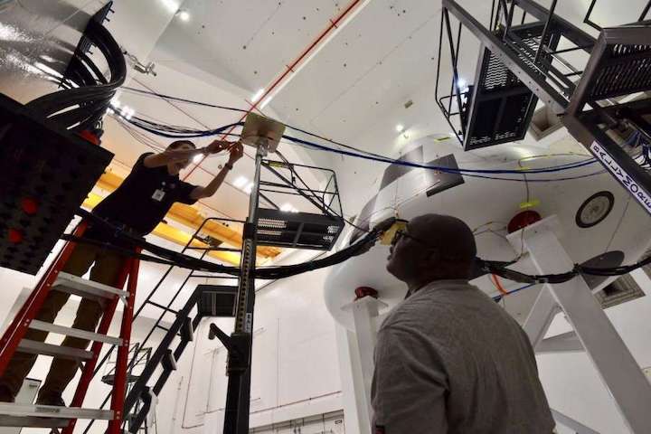
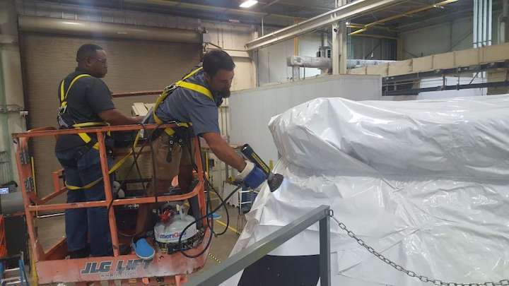
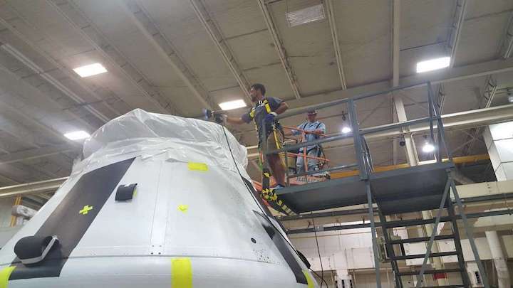
NASA personnel connect power and sensor cables used to track data during acoustic testing at NASA Glenn Research Center’s Plum Brook Station in Sandusky, Ohio, on Aug. 21, in preparation for Orion’s Ascent Abort-2 test.
Chasing Orion: This is the seventh in a series of stories leading up to the April 2019 launch of Orion's launch abort system, which is managed by NASA's Johnson Space Center in Houston.
The 35-day federal government shutdown ended last week, but the budgetary impasse continues to claim victims at NASA.
This time it is delaying an emergency system test for the Orion spacecraft being built to take humans back to the moon.
NASA officials confirmed this week that the launch of the Orion test module, previously scheduled for April from Cape Canaveral, Fla., would be delayed. They hope to determine a new launch date next week.
The new date "is going to be past where we were, but it's not going to be more than the duration of the shutdown," said Mark Kirasich, Orion program manager.
The launch will last just three minutes, but it will test the module's primary safety feature, known as the launch abort system. This system will allow the spacecraft's eventual four-person crew to escape if the rocket explodes.
The importance of this system was put on display worldwide in October, when the Russian Soyuz spacecraft transporting an American astronaut to the International Space Station had to abort its launch after a rocket booster failed, forcing an emergency landing.
The abort — Russia's first in 35 years — was a success, leaving NASA astronaut Nick Hague and Russian cosmonaut Alexey Ovchinin safe and in good condition. But the incident was a stark reminder of why such a system is so important — especially for a vehicle tasked with hauling humans back to the moon for the first time in 50 years.
The Orion spacecraft has been in various stages of design for nearly two decades, its destination shifting between the moon and Mars depending on White House leadership. But a return to the moon is a top priority for President Donald Trump's administration. His $19.9 billion proposed budget for the next fiscal year tasks NASA with launching an uncrewed Orion flight by 2021, followed by a launch of Americans around the moon in 2023.
Kirasich said the shutdown that started Dec. 22 because of a political battle over a border wall will not impact the schedule for the uncrewed Orion flight.
The punch line for [the uncrewed Orion flight]: the shutdown did not cause us to lose a day," he said. "It was very positive in terms of affecting the schedule."
Because the crewed flight is scheduled for so far out, he said it will be virtually impossible to determine if any delays were caused by the shutdown.
Much of the work on the test module was completed at Johnson Space Center in Houston, but officials in December transported it to Kennedy Space Center in Florida in preparation for its first and only flight.
The simplified module will not be reused once the test is complete. Additional capsules for the unmanned and crewed missions are under construction. The Space Launch System that will send Orion to space — the most powerful rocket NASA has ever built — and the ground systems for launch are being developed simultaneously.
Johnson personnel also are designing Orion's cockpit and flight software, spacesuits and parachutes. Johnson is home to the nation's astronaut corps, where human space flight research and training take place. It is also home to the International Space Station's mission operations and the Orion program.
From start to finish, the abort system test is expected to account for only $256 million of the program's more than $11 billion budget, according to NASA.