
11.08.2017
RS-25 Main Engine Controllers Tested for SLS Debut
STENNIS SPACE CENTER, Miss., Aug. 09, 2017 (GLOBE NEWSWIRE) -- Today at NASA's Stennis Space Center, Aerojet Rocketdyne, a subsidiary of Aerojet Rocketdyne Holdings, Inc. (NYSE:AJRD), tested its fourth RS-25 engine controller needed for the inaugural flight of NASA's Space Launch System (SLS) during Exploration Mission-1 (EM-1). Slated to debut in 2019, SLS will be the world's most powerful and versatile rocket.
"The SLS rocket will enable missions no other current rocket can, such as landing humans on Mars and sending large science payloads to other planets in record time," said Aerojet Rocketdyne CEO and President Eileen Drake. "This is the rocket the nation will rely on for decades."
Four RS-25 main engines built by Aerojet Rocketdyne provide more than two million pounds of thrust for the first stage of the SLS rocket. These are the world's most reliable rocket engines with 14 of 16 assigned to the SLS program having previously flown on the Space Shuttle. NASA and Aerojet Rocketdyne are testing the RS-25 engines to confirm they can withstand the SLS flight environment as well as certifying the new engine controllers.
New engine controllers are a central technology upgrade that these engines are receiving. These controllers weigh less, use less power and have fewer parts, but are more robust than their shuttle era counterparts and provide two times the reliability. The flight controller is the "brain" of the engine, translating the vehicle's commands into action while monitoring the health of the engine.
"The upgraded RS-25 engines are just one example of how the country is preparing a new course for deep space exploration," said Dan Adamski, RS-25 program director at Aerojet Rocketdyne. "EM-1 is the first step in a new roadmap to explore the solar system."
EM-1 is the first launch of the SLS and upgraded RS-25 engines; it is also the first integrated test of SLS and the Orion spacecraft. During the three-week mission, the Orion spacecraft will travel in a distant retrograde orbit around the moon and return safely back to Earth.
Quelle: Aerojet Rocketdyne
+++
RS-25 fires up again in another controller test for SLS

A little more than two weeks after the last test, the RS-25 test team acceptance tested the next completed engine controller unit (ECU) that will eventually fly on NASA’s Space Launch System (SLS) launch vehicle. Another flight-duration hot-fire of Development Engine 0528 (E0528) occurred Wednesday afternoon local time in the A-1 test stand at the Stennis Space Center (SSC) in Mississippi.
RS-25 Hot Fire:
Once again NASA, RS-25 prime contractor Aerojet Rocketdyne, and Stennis facilities contractor Syncom Space Services (S3) performed the test firing with the latest modern ECU built and delivered by Honeywell to Stennis.

Following the most recent hot-fire test on July 25, the latest controller was rotated onto the test engine to begin final preparations for the test.
Each RS-25 engine has a dedicated, self-redundant controller unit that controls its operation, monitors its health, and communicates with the launch vehicle flight computers.
Honeywell is building these new, modern units at their Clearwater, Florida, facility and as each of the flight model controllers are completed they are transported to Stennis, installed on an engine in the test stand, and hot-fired in an acceptance test (or “green run”).

Philip Benefield, Systems and Requirements Team Lead for the SLS Liquid Engines Office, said in an email that Wednesday’s test will green run the FM6 controller.
This is the fifth unit to be completed and the fourth to be hot-fired.
The FM2, FM3, and FM5 ECUs were green run on E0528 during the three most recent hot-fire tests on E0528 in March, May, and July, respectively.
As was the case for the tests of the other flight units, Wednesday’s test was planned to be a 500-second flight-duration firing, which is the approximate operating time of the RS-25 engines for SLS launches. The first flight model unit (FM1) is being used for lab testing only.
As with the last test in July, the test team at Stennis was again using the more typical event-driven approach. When all of the prerequisite steps prior to ignition are complete and the hardware and the people are ready, the test will start. “Assuming normal operations, [the] test will occur around 3 p.m.,” Benefield wrote. A 3 pm local or Central time start would be 2000 UTC. The ignition was timed at two minutes past the opening of the window.

Benefield said during the test that the engine will be throttled at thrust levels from 80 percent of rated power level (RPL) “up to and including” 109 percent. “[The] majority of the test will be spent at 109% RPL, 280 seconds,” he wrote. “35 seconds will be spent at 100% RPL, and 97 seconds will be spent at 80% RPL.”
Originally developed in the 1970s for the Space Shuttle Program when it was known as the Space Shuttle Main Engine (SSME), RS-25 hot-fire testing began at Stennis in January, 2015, to demonstrate and certify engine operation at the higher performance levels for SLS.
SLS is both physically longer and at times will accelerate faster during launch than Shuttle did, requiring different starting and running inlet conditions for the engines through powered flight.

Four engines will fly in the SLS Core Stage, burning cryogenic liquid hydrogen (LH2) and liquid oxygen (LOX) fed to them from the stage’s propellant tanks. The engines will run at higher pressures and higher thrust than on Shuttle, and the propellant is also fed to them at colder temperatures.
A new engine control system, including a new engine controller, is also being certified to fly with the SLS vehicle; this latest green run test of the flight model ECU also continues to accumulate the required data for certification.
Each test is designed to meet several test objectives, and although it is primarily an ECU green run, the test will also continue verification of SLS program requirements for the engines. During the test series, engines have been tested to demonstrate that they can start satisfactorily in a range of temperature and pressure conditions at its inlet. In the case of Wednesday’s test, Benefield wrote that “this will be a test at nominal propellant start conditions.”

Wednesday’s hot-fire was the eighth in a test series with E0528 that began in July of last year. So far, a total of fifteen tests have been conducted using both development engines (E0525 and E0528) and one flight engine retained from the Shuttle Program.
Certification of the new control system and controller also involves lab testing at Marshall Space Flight Center in Huntsville, Alabama, and at Aerojet Rocketdyne and Honeywell facilities in other parts of the United States. Qualification testing with the FM1 ECU is currently forecast to be completed in mid-September.
After the new controllers are green run, they are being removed from the development engine on the test stand and taken back to Aerojet Rocketdyne’s facility in Building 9101 at Stennis for integration with the flight engines that are stored there.
Until recently, the FM4 controller was scheduled to be tested as one of the units assigned to fly on the first SLS launch on Exploration Mission-1 (EM-1).
Originally, it was to be tested after the FM3 test in May and was expected to be the controller tested in Wednesday’s hot-fire. With both FM5 and FM6 now completed before that controller, it was unclear what FM4’s current status is.

Benefield noted that the controller tested in the last hot-fire test, FM5, performed well. “FM5 has been moved to SSC Building 9101 where it will be installed on EM-1 engine 2058,” he added.
A recent schedule has the four first-flight engines being checked out after the ECUs are installed and “delivered” at the end of the (Northern Hemisphere) Summer between the end of August and the end of September.
Plans were for the engines to remain at Stennis until some time next Spring, when they would make the relatively short trip to the Michoud Assembly Facility (MAF) in New Orleans where first Core Stage (CS-1) is under construction.
After the major CS-1 elements have been joined together and started final assembly at MAF, the engines will be installed horizontally in the engine section. Currently, the engines are assigned the following positions in the Core Stage: E2045 in position one, E2056 in position two, E2058 in position three, and E2060 in position four.
The next RS-25 hot-fire test planned at Stennis will green run flight engine 2063 (E2063) with another flight ECU. E2063 is one of two flight engines that haven’t been acceptance tested yet and it is expected to take E0528’s place in the A-1 test stand in late September for a test planned for October.
Quelle: NS
----
Update: 22.08.2017
.
Orion ESM begins hot fire testing at White Sands

The Orion European Service Module (ESM) Propulsion Qualification Module (PQM) is in the opening phases of testing – including hot firings – at the White Sands Test Facility in New Mexico. Bolted to a test stand, the PQM is being taken through a series of test campaigns by a team of personnel from prime contractor Airbus Defence and Space, the European Space Agency (ESA), and NASA.
Test objectives:
After initial propellant loading and characterization of subsystem behavior, hot-fire testing of the thrusters and engines to help qualify the propulsion subsystem of the ESM has just started.

“The number one purpose of this test activity is to qualify the propulsion subsystem,” Steve Barsi said in an interview with NASASpaceflight.com. Barsi is the ESM Propulsion Subsystem Manager in NASA’s Orion Program.
“This is one of the only subsystem verification activities that we have on the books. Normally you do testing at engine level or subassembly level, but the purpose of this test is really to bring everything together and try to test it in an integrated manner.
“[The ESM] engines have been tested at the thruster or engine level, but this is the first time where we’re bringing them all together and understanding interactions between the engines and what effects the [propellant] feed system has on the operation.”

The ESM has three types of engines: twenty-four reaction control system (RCS) thrusters for attitude control, eight auxiliary engines for translational maneuvers, and an Orbital Maneuvering System engine (OMS-E)for large translational burns. The PQM only has twelve RCS thrusters, omitting one of the twelve-thruster RCS “strings.”
Although the RCS thrusters and the auxiliary engines are undergoing individual hot-fire testing above and beyond these tests, the PQM testing also provides an opportunity to hot-fire the main OMS-E engine.
Originally the main engine for the Space Shuttle Orbital Maneuvering System, it was re-purposed for the ESM. Although the engine used in these tests will only be used for ground testing, this will be the first time OMS engines have been fired since the Shuttle era.
“A second pretty big objective [of the PQM tests] is to go delta-qualify the OMS engine,” Barsi explained. “Over the past probably two years or so, we’ve been readying the OMS engine for flight. That involved using a Shuttle engine, taking it apart, rebuilding it and it underwent environmental qualification testing at the Johnson Space Center.

“The specific objective related to the OMS engine is after it was subjected to a vibration environment that exceeded its previous use on Shuttle, we want to confirm that the engine can still operate normally under the environment that it’s expected to see in flight.”
Airbus Defence and Space is the prime contractor for the ESM; in addition to the propulsion subsystem being tested with the PQM, the flight model ESM also provides electrical power, thermal control, and consumable storage for the overall Orion spacecraft.
Final integration of the PQM was done by OHB Sweden in Stockholm, which was completed in January. The module was then shipped to the United States and arrived at White Sands in February for initial installation in Test Stand 301 there.
Test campaigns:
In addition to the engines, the PQM has propellant storage and distribution and pressurization assemblies, along with avionics for their command and control. Mr. Barsi said the initial hot-fire tests will look at the system behavior without pressure control.
“The test campaign is phased over two parts. The first part is related to blowdown testing — what I mean by that is there’s no active pressure regulation of the propellant tanks.

“We’re trying to get some early data and these are shorter duration burns — it’s not actively controlling the pressure in the propellant tanks. That total test campaign is approximately three weeks.
“The next phase of testing is active pressure regulation and so we’re still waiting on some hardware to perform that testing and that should arrive later this year. Once that hardware arrives and it’s integrated we’re looking at a few months of testing.”
The test team consists of approximately thirty people, including personnel from Airbus (both on-site at White Sands and in Bremen, Germany), ESA (in White Sands and Europe), and NASA (from White Sands and Glenn Research Center). The on-site personnel will be working from a blockhouse near the test stand.
“It’s within walking distance of the test cell, but it’s far enough away to keep those safety limits that have been defined,” Barsi noted. The ESM uses hypergolic propellants which are highly toxic; mixed oxides of nitrogen (MON-3) is the oxidizer and monomethylhydrazine (MMH) is the fuel.

The overall test campaign is divided up into different phases and will hot-fire different combinations of the engines.
“There’s about six overall separate campaigns,” Barsi added. “The different campaigns are intended to test different things, so some of the specific campaigns evaluate system performance with saturated versus unsaturated propellant. That’s referring to the amount of helium dissolved in the fuel and the oxidizer.
“Some of the sequences have to do with running through specific burn sequences, so we’re looking at firing the auxiliary engines and the OMS engine simultaneously. And then we’re looking at firing the aux engines and the RCS engines simultaneously and looking to see if there are any pressure transients in the system.”
Each of the test campaigns also has several sequences within it.
“There are multiple sequences and each sequence has multiple firings in it. We use inputs from the Guidance Navigation and Control (GNC) team to help define what those sequences are. Some of the sequences are pretty short — so the first test we do is just doing short firings of the engines just to do a general health check on the system.
“This will be the first time we’re firing engines with the accompanying ESM propulsion feed system. So some sequences just have single burns in them [and] some have multiple engine burns — it’s all intended to qualify the subsystem.”
“The most stressing case from a subsystem burn profile is an abort profile — that’s the profile where all the engines are firing at the same time,” he noted, adding that in an abort the engines could run around twice as long as a more typical burn.
Test configuration:
The PQM will be operated in ambient conditions for these tests as compared to normal operation in Earth orbit or cislunar space, with some provisions for that environment.
 “[We have] a diffuser with a blowoff plate, so…some of the [tests] we’re going to be running with a simulated vacuum start for the OMS engine,” Barsi noted.
In addition to the single-string RCS on the PQM versus flight models, the PQM structure and propellant tanks are also different, but Barsi explained that the qualification article is being used to focus on characterizing the behavior of propellant distribution, pressurization of the system, and engine firings.
“Structurally it’s a much beefier system, the ground article. The tanks are much beefier, too; but in terms of what we’re looking to get out the test, all the line routing geometry are the same. That’s a pretty important parameter to understand what the pressure drop is from the tanks to the engines and understand what the overall hydraulic performance of the system is.

“All the engines are flight-representative, most of the valves are flight-representative. The big differences are structure and the propellant tanks.”
The avionics for the propulsion subsystem are also contained with the PQM.
“The way the subsystem is structured, the active regulation unit and avionics for that…[are] part of the subsystem,” Barsi continued. “So that is flight representative; there’s obviously not a flight computer for the PQM, there’s a ground computer that supposed to send commands to activate specific burn sequences.
Both the flight models and the PQM use helium to pressurize the propellant tanks, but Barsi noted that the OMS engine retains it’s own pressurization pack.
“The OMS carries its own little tank and that’s nitrogen and that’s used to pneumatically actuate some of the valves and then purge the engine of fuel at the end of every burn,” he noted.
Barsi said that the test campaigns are planned to be completed early next year. After that, the PQM will be decontaminated and eventually will be removed from the test stand.
Quelle: NS
---
Update: 23.08.2017
.
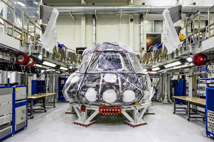
"Orion was designed from the beginning to take humanity farther into space than we've ever gone, and to do this, its systems have to be very robust and reliable."
DENVER, Engineers at Lockheed Martin (NYSE: LMT) and NASA breathed life into the next Orion crew module when they powered up the spacecraft for the first time at the Kennedy Space Center, Florida. Designed for human spaceflight, this Orion will be the first to fly more than 40,000 miles beyond the Moon during its nearly three-week Exploration Mission-1 (EM-1), a feat that hasn't been possible before.
"Orion was designed from the beginning to take humanity farther into space than we've ever gone, and to do this, its systems have to be very robust and reliable," said Mike Hawes, vice president and Orion program manager at Lockheed Martin. "Over the last year, we've built great momentum in assembling the crew module for EM-1. Everyone on the team understands how crucial this test campaign is, and more importantly, what this spacecraft and mission means to our country and future human space flight."
The initial power-on event was the first time the vehicle management computers and the power and data units were installed on the crew module, loaded with flight software and tested. Evaluating these core systems, thought of as the "brain and heart" of the Orion capsule, is the first step in testing all of the crew module subsystems.
Although astronauts will not fly in this capsule on this flight, a large majority of the subsystems and avionics are the same design that astronauts will rely on during following missions with Orion into the solar system. Launching on NASA's Space Launch System—the most powerful rocket in the world—the EM-1 flight is critical to confirming the Orion spacecraft and all of its interdependent systems operate as designed in the unforgiving environment of deep space.
With the successful initial power on behind them, engineers and technicians will now continue integrating the 55 components that make up the spacecraft avionics suite, connecting them with nearly 400 harnesses. Over the course of the next two to three months, as each system is installed, they will perform thorough functional tests to ensure Orion is ready to move to the all-important environmental testing phase.
NASA's Orion multi-purpose crew vehicle is the world's first human-rated spacecraft designed for long-duration, deep space exploration. Orion will transport humans to interplanetary destinations beyond low Earth orbit, including the Moon and eventually Mars. Lockheed Martin is the prime contractor to NASA for Orion, and is responsible for the design, build, testing, launch processing and mission operations of the spacecraft. Orion is managed out of NASA's Johnson Space Center in Houston.
Quelle: Lockheed Martin
+++
By Staff Writers
NASA's John F. Kennedy Space Center
Hurtling beyond the Moon at a speedy 25,000 mph for a three-week mission requires a space processor capable of operating with guaranteed reliability, in a high radiation environment tens of thousands of miles in deep space, at 480,000,000 instructions per second to execute thousands of commands and sequences for controlling the hundreds of spacecraft systems and components to ensure crew safety and mission success.
To ensure everything performs as planned, the Orion spacecraft destined for Exploration Mission-1 was successfully powered up for the first time this week in Orion’s spacecraft factory, the Neil Armstrong Operations and Checkout Facility at NASA’s Kennedy Space Center in Florida.
“The initial power-on procedure verified the health and status of Orion’s core computers and power and data units and marks the beginning of critical spacecraft subsystem tests to get us ready for flight," said Mark Kirasich, NASA Orion program manager. “Our test team, ground support equipment and flight systems all performed remarkably well during the test. This is a major milestone for Orion and for our long range deep space exploration plans.”
During the initial power-on tests, engineers and technicians connected the vehicle management computers to Orion’s power and data units to ensure the systems communicate precisely with one another to accurately route power and functional commands throughout the spacecraft for the duration of a deep-space exploration mission. In spaceflight, Orion will generate power through its four solar array wings which collectively hold about 15,000 solar cells that can harness enough electricity to power eight three-bedroom homes. The power and data units then distribute that power as needed throughout the spacecraft.
“The spacecraft’s power and data units and core computers will continue to undergo additional testing of various components over the next two to three months,” said Rafael Garcia, NASA Orion program test and verification lead at Kennedy.
Orion will launch atop the agency's Space Launch System rocket for an uncrewed mission traveling 40,000 miles beyond the Moon and returning to Earth with a Pacific Ocean splashdown. The mission will demonstrate the integrated system performance of the rocket, Orion spacecraft and ground support teams prior to the first flight with astronauts on board.
Quelle: NASA
---
Update: 27.08.2017
.
Wind Tunnel Test of Deep Space Rocket Calls For New Coat of Paint
 Bill Lipford is painting a scaled model of the Space Launch System at NASA's Langley Research Center. Credits: NASA/David C. Bowman |
NASA's most advanced launch vehicle is undergoing a variety of testing before the Space Launch System (SLS) rocket will be used to launch astronauts in the agency's Orion spacecraft on missions to explore deep space. In one particular series of tests, this advanced piece of machinery is getting a fresh coat of paint.
At NASA's Langley Research Center in Hampton, Virginia, a scaled model of the SLS is undergoing testing using pressure-sensitive paint to evaluate the separation of the left and right solid rocket boosters from the rocket's core. The painted model undergoes testing at Mach 4 (3,069 mph or 4,939 km/h) for the Block 1B cargo and crew vehicle.
"This is an important aerodynamic test in assuring that the boosters will cleanly separate from the center core of the vehicle and not pose a hazard to mission success," said David Piatak, acting co-lead for Langley's SLS Aerodynamics Team.
"The aerodynamic data from the previous round of testing was very helpful to the larger SLS team in determining clearances for the booster separation of the first-generation rocket," Favaregh said. "That information has helped shape decisions on booster separation timing in the trajectory."
"We're testing all the locations that the boosters could be at in relation to the core as they fall away," said Courtney Winski, a researcher at Langley's Configuration Aerodynamics Branch.
The solid rocket boosters on the side of the SLS act like extremely short stubby wings and can sometimes have surprising impacts on the system aerodynamics, said Amber Favaregh, acting co-lead for Langley's SLS Aerodynamics Team.
Pressure-sensitive paint allows engineers to gain "a visual of the flow and pressure on the model during separation," Winski said. "It gives us more data on how it is going to separate, and possible effects on flow path."
A similar SLS model, also tested at Langley's Unitary Plan Wind Tunnel, underwent testing for the Exploration Mission-1, which will be an uncrewed test flight. The rocket will send the Orion spacecraft on a mission travel thousands of miles beyond the Moon over the course of about three weeks.
Langley isn't the only NASA center putting a SLS model through testing using pressure-sensitive paint, as NASA's Ames Research Center in California's Silicon Valley has done examinations using the paint.
This round of testing with the specialized paint job "uses high pressure air to simulate the exhaust plumes of SLS to allow us the opportunity to validate the very complicated flow fields being evaluated by computational fluid dynamics," she said.
Computational fluid dynamics is a branch of fluid mechanics that relies on a supercomputer for numerical analysis and data structures to solve and analyze problems. Testing in wind tunnels helps to supplement and validate the data from the computations, and can also uncover unanticipated findings.
"You find new things all the time," Winski said.
"This rocket must get up to 17,500 mph (28,163 km/h) to reach orbit and pass through the Earth's thick lower atmosphere at transonic and low-supersonic speeds where aerodynamic forces play a large role in the structural design of the vehicle, in addition to keeping the pointy-end moving toward its orbital target," Piatak said. "So we must perform a great deal of ground testing in wind tunnels to measure the aerodynamic forces on the vehicle as it plows through the atmosphere on its way to orbit."
Even after the launch, engineers will continue to analyze more data received on the rocket's actual performance during the real-world conditions of launch, outside of the wind tunnel.
"I'm positive it will be a surreal experience to watch our rocket successfully launch," Favaregh said. "I imagine some joyful tears and a lot of celebration. All that excitement will be followed by the excitement to take all that flight data and implement it in future configurations and variants of the SLS to keep pushing the boundaries of space exploration."
Quelle: SD
---
Update: 6.09.2017
.
SLS Core Stage Pathfinder prepares for barge ride to MAF

A full-scale model of a Space Launch System (SLS) Core Stage, called the Core Stage Pathfinder, was recently completed at a plant in Northern Alabama, and will soon be shipped and turned over to NASA. A ceremony was held to mark the completion of construction and assembly of the gigantic steel article at G&G Steel’s even more enormous facility in Cordova, Alabama.
SLS Core Pathfinder:
Radiance Technologies and Dynetics were contracted by NASA to build and deliver the Pathfinder; G&G Steel performed the final welding and assembly of the steel structure.

The companies will turn over Pathfinder to NASA after they deliver it by barge from G&G’s Cordova facility on the Black Warrior River to the Michoud Assembly Facility (MAF) in New Orleans, Louisiana, sometime in the next month or so.
NASA will use Pathfinder at MAF, the Stennis Space Center (SSC) in Mississippi, and the Kennedy Space Center (KSC) in Florida to practice handling the size and weight of a fully assembled SLS Core Stage at those different locations and transportation between them before they have to start doing it with the real thing as early as next year.
The Pathfinder was designed to mimic the “form and fit” of a real Core Stage. It has the same weight, center of gravity, size and shape as a finished, empty SLS Core Stage, which is how the rocket will be delivered by barge from MAF to Stennis and/or KSC.
The Pathfinder weighs about 228,000 pounds, is about twenty-seven and a half feet in diameter, and about 212 feet in length from the top of the forward skirt to the bottom of the engine nozzles.

“This has all the interfaces that we need at all different facilities and all different GSE (Ground Support Equipment) for transportation,” Tim Flores, integration manager for the SLS Stages Element Office, said in an interview at the event.
“This has the flight-like interfaces. So the pads on this Pathfinder are flight-like. [The] SRB fittings, those are the most expensive part on here, they’re flight-like fittings.”
In addition to things like SRB attachment fittings, the Pathfinder has or will have elements that simulate some of the larger protuberances on the outside of the stage, such as the systems tunnel and the liquid oxygen feedlines, also known as downcomers. Both the systems tunnel and the two downcomers run along most of the length of the stage.
“[Learning] where your clearances [are], that’s a big thing and there’s some places where there’s just not very much clearance and knowing where those are [is important],” Flores noted. “So we’re trying to put everything that’s going to be [on the Core Stage] on there.”

Pathfinder has wire-frame simulators of the RS-25 engine nozzles at the bottom of the stage, with fins forward of that to simulate the boat tail fairings. “They made the [simulated] engines [so] there’s one little piece that sticks out a little bit further and I believe that just gets the dimension of that without putting the whole fairing there,” he added.
After the Pathfinder gets to MAF, the remaining simulated elements that need to be added will be attached there.
“There’s some additional hardware that is very low fidelity that they’re not going to add until it gets [to MAF] and that is the downcomers,” Flores noted. “They’re going to add that, but they’re not going to until they get there, because it’s very flimsy.
Although the Pathfinder is just as large and heavy as a Core Stage, it is not structurally engineered like one. “It’s just form and fit, it’s not function,” Flores added.
For the testing that NASA has planned, the article will also keep its current flat gray primer appearance, in contrast to the foam-covered, orange and white real thing. “All we’ve got on it right now is primer,” Flores explained.
“We’re not going to paint it because it wasn’t going to add anything to it other than weight and money. So we went with just primer, which should be OK [and] can handle the weather.”
Lift spiders:
In addition to the Pathfinder, G&G Steel is completing two massive lift “spiders” at the Cordova facility that will also soon be delivered to NASA. One of the spiders and a lift ring were on display at the ceremony and the second spider was being completed elsewhere in the facility.

“The spiders are used in two different places,” Flores explained. “[They are] used at Stennis to lift and break over and also in the VAB they’ll use it there. The lift ring goes in between that and the front face of the forward skirt and it’s got the mechanism to be able to put a weather cover on it also.
“So when you’re in [the test stand at] Stennis, you’re not dripping everything down inside there – it’ll actually be protected. It’s not out here, the weather cover. Boeing (the prime contractor for the core stage) is producing that – we don’t need it for [Pathfinder].”
The spiders themselves are big and weigh about 45000 pounds each. “It is beefy structure,” Flores said, noting that the spider is too heavy to leave bolted on the structure when it is oriented horizontally.
“Pathfinder can’t take that weight. And to tell you the truth, Core Stage can’t take that weight. So when we transport it, we have to take the spider off. You just can’t carry [the lift spider] around as you move around and that thing is cantilevered out there. Structurally, [a Core Stage] doesn’t handle it and the Pathfinder without a doubt doesn’t handle it.”

Flores explained that a different piece of GSE will help support the weight of the spider, noting that “when it goes on the front we actually have what’s called a TIF, Transportation Interface Fixture, and it holds it upright.”
The Pathfinder and the lift spiders will be delivered to NASA on commercial barges, leaving Cordova once some final work is completed.
“[In] about two weeks, give or take,” Sam Stephens, manager for wet structures in the SLS Stages Office, said at the event regarding the timing of the departure.
“They’ve still got a few more operations to do, they’ve got to finish up the second spider, proof test it, [and then] they’ll go on the barge. I don’t know if [former Hurricane] Harvey is going to affect things. They’ve got to get a barge up from New Orleans, so there’s all those logistics we have to work with.”
Next On The Path:
Once at MAF and turned over to NASA, the Pathfinder will start off outside.
“Actually, it will be sitting in the parking lot of [Building] 303 or out on the apron,” Stephens said. “Because this doesn’t need to be out of the weather and it takes up a lot of real estate as you can see.”

“One of the first things that we’re going to do at MAF is, you see the SRB fittings that are on there, it’s actually complicated to get those things pinned and get some of the hardware on that to actually run with the GSE and for the Boeing lifting capability,” Flores explained.
“The GSE won’t quite be there when this gets there, so we’re building some platforms where we can go and we can actually do the practice of changing out the hardware. The hardware is extremely heavy, hundreds of pounds in some cases, so that’s one of the things that we’ll do immediately.”
While at MAF, the Pathfinder will give NASA and Boeing a chance to practice and improve the operational sequences to deliver a completed Core Stage at the end of production.
“What we want to do over at MAF is actually run through the paces between Boeing’s final assembly and then going from there over to our GSEs, Flores explained.
“They are going to be assembling a Core Stage and then it will be put from their rigs over to our GSE. We want to go through those paces, so that’s one of the things we’re negotiating right now with Boeing to make sure that happens.
“One of the GSE systems that’s called the MPTS (Multipurpose Transportation System) will connect up to the SRB fittings and then one will connect in the back and we’ll pin in four places, just like the STAs (Structural Test Articles) so that connection on the Core Stage is exactly like we do on the STAs. Well, they’re not simple connections. We’re getting to practice right now with pinning on the back end – or we will – with the STAs and something we call the DDU (Dynamic Demonstration Unit).
“We’re practicing with the GSE right now with that. We’ll run through those paces and make sure we understand how the different fittings fit, because we don’t have anything that meets the interfaces of Core Stage other than [the Pathfinder].”
Robotic, motorized transporters called self-propelled modular transporters or SPMTs will pick up the MPTS that the Core Stage attaches to.
Once the stage is placed and secured on the SPMTs, it can then be rolled along an approximately mile-long road route on MAF property, out from Building 103 to the dock where NASA’s Pegasus barge is. The SPMTs will then be used to roll the stage with its GSE onto Pegasus, where they will be physically secured.
The Pathfinder is configured so that personnel at MAF can practice this series of steps multiple times and in both directions between Final Assembly and Pegasus.
Future testing:
Early next year, the plan is for the SPMTs to move Pathfinder onto Pegasus and after it is secured, the barge will be taken from MAF to the relatively nearby Stennis Space Center in Mississippi. The barge will travel to the B-1/B-2 test stand at Stennis, where the renovated and extended B-2 stand is being readied for Core Stage green run testing.

Given that Pathfinder simulates a Core Stage’s form and fit, this will be an early exercise for the Pegasus barge crew making a trip with its largest, heaviest payload, and also gives them a chance to evaluate their transportation plans.
As at MAF, Pathfinder will allow personnel at Stennis to practice handling operations there. Just like the real Core Stage, Pathfinder will be rolled off the barge at Stennis and lifting GSE (including one of the lift spiders) will help cranes attach to it. The article will be lifted up off the SPMTs and rotated to vertical; this “break-over” operation will be practiced multiple times.
The Pathfinder will then be lifted up and into the B-2 stand where the attach fittings will be used to bolt it into the stand. The opposite sequence of removing the Pathfinder from the stand, breaking it over from vertical to horizontal, putting it back on the transportation GSE, and rolling back onto the barge will also be practiced.
“We’ll practice lifting it, breaking it over, and then putting it into the B-2 stand. Hopefully, we can go through that process two or three times at least,” Stephens said.
Unlike the real stage that has umbilical panels where all the required services can be fed into the rocket, the Pathfinder has only stickers or placards to indicate their locations.
Stephens explained that this will give both Stennis and Kennedy another check on the positioning of their ground side umbilicals, noting “things that we’re not attaching such as umbilicals, we just use stickers – decals positioned at the right spots so when we do position them at Kennedy or at Stennis, we can line up and go ‘yup, we’re in the right spot, it’s where we expected, it’s all good.'”
Once all the handling tests at Stennis are complete, the Pathfinder will go back onto Pegasus, which will make the much longer voyage from Stennis to KSC, giving the Pegasus crew an opportunity to practice the same trip they will take with the real Core Stage after green run testing is complete.
At KSC, ground crews there will get a chance to test their handling procedures – rolling the Pathfinder on the SPMTs off the barge at the upgraded Turn Basin at Launch Complex 39 into the VAB Transfer Aisle, where crane operations can be tested.

The Pathfinder will allow lift to mate operations in the VAB to be practiced, where the stage will be lifted off the SPMTs in the Transfer Aisle, broken over to vertical, lifted up towards the top of the VAB, through the High Bay 3 diaphragm, and down towards the deck of the Mobile Launcher.
In the case of Pathfinder, there won’t necessarily be anything it can attach to during these practice dry-runs. “It’s not set up to actually connect to the boosters,” Flores explained.
“If Kennedy had an opportunity to try to do something [like] connecting Pathfinder up to the boosters, we haven’t talked with them about that. But we’re leaving Pathfinder at Kennedy, so there will be more time for them to do some practicing and if there’s opportunities like that, they can seek them out.”
Although the reason for Pathfinder’s existence is still in front of it, there has been some thought about a final resting place when its work is complete.
“We’ve already been talking with the [U.S.] Space and Rocket Center (in Huntsville) about whether or not they can have it as some kind of a display,” Flores noted. “They’re working that, not at the [NASA] Headquarters level but at the center director level. They’re making plans to do something with it [and not] let this go out to some boneyard.”
Quelle: NS