
.
 Apollo Lenticular Credit: Mark Wade |
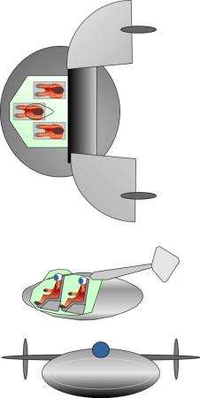
American manned spacecraft. Study 1962. The Convair/Astronautics alternate Lenticular Apollo was a flying saucer configuration with the highest hypersonic lift to drag ratio (4.4) of any proposed design.
Status: Study 1962. Gross mass: 8,778 kg (19,352 lb). Height: 9.76 m (32.02 ft). Span: 4.88 m (16.01 ft).
The lenticular shape, with deployable wings for final approach, had first been suggested by Alan B. Kehlet of STG's New Projects Panel in 1959. The compact circumlunar version of the spacecraft was only 9.76 m long but also the heaviest Apollo proposed at 8,778 kg.
The saucer was 4.88 m in diameter but only 1.73 m deep, with a total mass of 2867 kg. The unique shape required reverse packaging at launch. Within a large conical shroud the propulsion module was at the top, followed by the saucer, then the pressurized mission module. The crew's seats were set back 90 degrees for launch, then brought upright for normal operations and landing. Access to the mission module was through a hatch in the bottom of the saucer.
Unlike the other Apollo designs, the lenticular required different propulsion and mission modules compared to the M-1 baseline. The lenticular design also provided difficult engineering problems in launch escape and arrangement of the modules. Although favored by many at NASA headquarters, the simpler ballistic approach won out in the end. The lenticular design was further developed by North American for the US Air Force as a 'space bomber' in the early 1960's.
Family: Lenticular Vehicles, Manned spacecraft. Country: USA. Launch Vehicles: Saturn I, Saturn V. Agency: Convair.
 |
Apollo Lenticular Credit: NASA |
ROOST and Astro
Credit: NASA
American manned spaceplane. Study 1963. In 1963 Phil Bono of Douglas Aircraft considered a lenticular configuration for a single-stage-to-orbit reusable booster. This was the largest application found to date for the lenticular concept.
Status: Study 1963. Payload: 454,000 kg (1,000,000 lb). Gross mass: 20,400,000 kg (44,900,000 lb). Unfuelled mass: 1,940,000 kg (4,270,000 lb). Specific impulse: 410 s. Height: 120.00 m (390.00 ft). Span: 108.00 m (354.00 ft).
The 108-m diameter saucer would have delivered a million pounds of payload to low earth orbit. It was assessed as having a slightly inferior mass fraction to the baseline cylindrical ROOST design (0.925 versus 0.930) and a significantly higher delta-V requirement due to increased drag (9450 m/s total impulsive requirement vs 9100 m/s for the preferred ROOST concept). This drove the gross lift-off mass at the assumed vacuum specific impulse of 410 seconds to 45 million pounds versus 25 million pounds for the ROOST baseline. The design evidently went no further than a notional concept in the trade study.
Spacecraft delta v: 9,450 m/s (31,000 ft/sec).
Family: Lenticular Vehicles, Spaceplane. Country: USA. Propellants: Lox/LH2. Agency: Douglas. Bibliography: 214.
 NAA Space Bomber |
American manned combat spacecraft. Study 1963. In the early 1960's, one configuration studied by North American Aviation for the USAF space bomber study was this 12-m-diameter flying saucer design.
Status: Study 1963.
A crew of four would have patrolled space for six weeks, with four thermonuclear weapons as armament.
This lenticular design was one concept for a manned reconnaissance and bomber spacecraft considered in 1962 by North American Aviation under a USAF study for deployment in the 1965 to 1975 period. The crew of four would have remained in orbit on missions of up to six weeks. A sensational article appeared in Popular Mechanics in November 2000 claiming that this was a nuclear-powered bomber, based on German World War II designs. It alleged it was part of a development lineage running through covert projects of the 1950's such as Silverbug and Pye Wacket. It was further alleged that some honeycomb fiberglass/aluminum wreckage found in Australia in 1975 was related to actual flight tests of this vehicle - however the North American design was of much more exotic materials.
In fact, this was just one of four re-entry vehicle concepts (lifting body, winged, ballistic, lenticular) studied by North American for a USAF study on a manned orbital nuclear deterrent system. And rather than being based on the mentioned projects (which used the saucer shape for different reasons), the very likely source for the design was Alan Kehlet, a NASA aerodynamicist. He had advocated the lenticular re-entry vehicle for Project Apollo, and had been hired by North American just the year before.
Contrary to other allegations made in the Popular Science article, the spacecraft was not to be nuclear powered. A nuclear power source was one alternative considered for the 7 kW electrical system, but the engineering and safety analysis indicated a solar-thermal system would be more effective.
Perhaps more interesting was the systems concept considered. This was nothing less than a space-based version of the Minuteman ICBM system. The lenticular vehicle would just be the command post, waiting to authorize the go command to dozens of nuclear warheads orbiting nearby in unmanned weapons clusters. Except for the (unnecessary) aspect of having a manned platform to order an attack on the Soviet Union, this was similar to some Star Wars concepts of the 1980's. The overall weapon system concept consisted of three basic orbiting components:
- The Manned Bombardment and Control Vehicle, which housed the basic control function in space and was itself armed with up to four thermonuclear weapons. This was the only portion of the system which was required to repeatedly reenter the earth's atmosphere. The Bombardment Vehicle could command, service, and launch on command the warheads from several Weapons Clusters.
- The Weapons Cluster, an unmanned weapons platform which integrated several thermonuclear weapons into a common orbiting package to facilitate handling and servicing. This included 320 kg of propellant for topping up the tanks of the weapons. A manned interorbital shuttle vehicle would travel from the Bombardment Vehicle to each cluster every six weeks, refueling the cluster propellant tank and servicing the weapons as needed. Top-off propellant requirements for the cluster and for the weapons would be small; estimated to be less than 22 kg per complete cluster per six week period.
- The orbiting thermonuclear weapon itself. Each winged re-entry vehicles was 7 m long, 50 cm in diameter, and had a wingspan of 1.4 m. Their total mass of 913 kg, included 90 kg of propellants. This would be sufficient for a delta-V of 300 m/s, enough, in conjunction with the delta wings, to attack Soviet targets, under the radar, without warning, up to two thousand kilometers left or right of the orbital ground track.
Bombardment and Control Vehicle
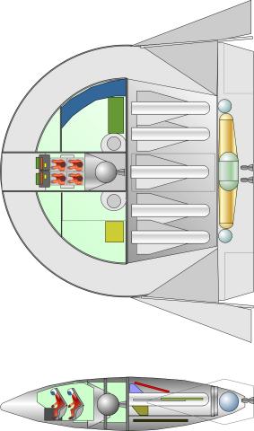
The Bombardment and Control Vehicle was the primary element of the system, and functioned as a manned orbital bombing system with an internal armament load of four winged reentry weapons and also acted as an orbital control and maintenance center for additional unmanned weapon clusters. The disc-shaped configuration was chosen for its greater usable volume available for weapons storage, crew accommodations, and for other unmentioned advantages. It had a basic diameter of 12.2 m and a gross launch mass of about 20,500 kg. The design operational mission was of six weeks duration, with a crew of four men at a nominal orbital altitude of 560 km. The vehicle incorporated a jettisonable crew compartment capsule for emergency escape and an interorbital shuttle service vehicle for inspection and maintenance of the weapon clusters.
The total projected planform area was 144 square meters which resulted in a normal reentry and landing wing loading of approximately one kilogram per square meter. The projected planform included the horizontal area between the disc and the straight trailing edge, which provided the flap area and also included the movable horizontal stabilizer surface located outboard of the vertical stabilizer surfaces. The hinged trailing edge surfaces inboard of the verticals functioned as elevators during subsonic flight and landing. The all movable horizontal surfaces located outboard of the verticals could be differentially actuated to provide roll control as well as simultaneously to provide pitch control, and were effective throughout the entire flight regime. The landing gear consisted of retractable skids mounted on the lower fuselage surface.
The useful load was 12,514 kg included 3650 kg for the four winged weapons. The vehicle was designed with four primary internal compartments: the living quarters, work area, armament bay, and crew escape capsule. Each compartment could be individually isolated from the other three, should a puncture or leak make one temporarily unusable. Repairs could be made to the damaged compartment while the crew used the remaining compartments for living and working quarters.
The crew capsule functioned as the vehicle control center during normal operation and as the crew escape capsule for an emergency abort of the mission. The escape capsule was actually a breakaway nose section of the vehicle, approximately 5.2 m long and 1.8 m wide. The capsule separated the crew living quarters from the work area and provided access to either compartment through a door in each side of the capsule. A sealant material around the doors prevented leakage of the cabin air during normal operation and was broken only when the capsule was separated from the primary vehicle.
The abort capsule contained the crew stations for boost and reentry, the vehicle control consoles, and the emergency power supply and life support equipment needed for an abort mission. Exit from the capsule after an abort was provided by the doors on each side, which served as the passageway doors between the compartments in normal operation.
Separation of the capsule from the main bomber vehicle was accomplished with a 220 kN thrust, spherical, solid propellant rocket engine located at the aft section of the escape capsule. The engine burned for 10 seconds and imparted an initial acceleration of 8.5 g to the capsule, sufficient to escape the 0.3 bar overpressure wave resulting from an explosion of the first stage booster during launch from the pad. The 10-second burning duration ensured sufficient altitude above the pad at burnout to permit recovery of the capsule with a parachute located in the forward nose section of the capsule, which was enclosed within a jettisonable nose fairing. The recovery chute was sized to limit the impact velocity of the capsule to approximately 7.5 meters per second.
Stabilization of the capsule was via four foldout fins located on the aft section. Over-nose vision for a normal vehicle landing was provided by translating the nose section downward and exposing a flat plate windshield in the forward pressure bulkhead of the capsule. This window could also be used by crew for external viewing while in orbit, but was covered during ascent and reentry.
The environment of the crew capsule, living quarters area, and working area compartments was maintained for shirt-sleeve operation during the orbital mission. However, all compartments contained sufficient volume for crew operation in space suits. The cabin was pressurized to 0.68 bar limit continuously from 3 km altitude in the boost phase through the 6-week orbiting flight and reentry back to 3 km altitude.
The off-duty area was the living quarters for the crew and was located on the starboard aide of the vehicle. The area was designed with sufficient volume and flow area to provide comfortable living quarters and recreational area for the crew during the extended mission duration of 6 weeks. The compartment contained sleeping and sanitation provisions, food storage and separation facilities, stowable table, chairs, and exercise equipment. Sleeping nets with storage space below for personal gear, books, etc, were located along the wall. Food storage and preparation facilities, plus miscellaneous storage provisions, were located along the other wall. An airlock compartment provided access from the pressurized off-duty area to the unpressurized weapons bay, or to the outside of the vehicle. Access to the on-duty work area was through the vehicle control compartment.
The on-duty work area was located on the opposite side of the vehicle. The work area contained all the display consoles and control equipment for launching, monitoring, and controlling the weapons and controlling the unmanned weapon clusters, the primary electronic equipment, and miscellaneous tools and maintenance equipment. A generous allowance of volume for the display consoles and electronic weapon control equipment permitted easy access to all the equipment for maintenance and repair. The primary environmental control, power supply and miscellaneous vehicle support equipment was located around the forward periphery of the off-duty and on-duty compartments. The central floor area of the work area was kept open to permit freedom of movement for the crew for maximum efficiency and convenience. Access to the outside and to the weapon storage area was via an interconnecting airlock compartment.
The weapon storage compartment was located in the aft section of the vehicle on each aide of the weapon launch bay and provided storage space for four winged weapons - two on each side of the displacing mechanism which was located on the lift coefficient of the vehicle. The weapon storage area was an unpressurized compartment and was accessible from both the on-duty and off-duty crew compartments through airlocks.
Sufficient space was provided for access to the weapons in the storage area for maintenance, repair, checkout, and launch procedures. The weapons were supported on rails in the storage area which permitted manual transfer of the weapons from the stored position to the displacing mechanism for launch. During the orbital phase of the mission, all weapons would be transferred, via the displacing mechanism, after the shuttle vehicle was removed, and attached to the external surface of the vehicle in ready position. The shuttle was then returned to the displacing mechanism and the vehicle was ready to initiate a strike using the attached weapons or using remotely located clustered weapons. The vehicle was also in position to make an immediate reentry, in case of emergency, by simply detaching the four weapons and leaving them in space to be recovered at a later time.
Alternatively the weapons storage compartment could be used to transport fuel or replacement parts as needed for repair of the unmanned weapons clusters.
The basic disc shape was inherently unstable with typical expected center of gravity locations. However the use of suitably located flaps, control surfaces, and speed brakes were expected to result in a vehicle with outstanding aerodynamic performance. The disc would have a subsonic L/D ratio of 9.0, a supersonic L/D of 2.0, and a hypersonic L/D of 1.5 during reentry. This maximum L/D of 1.5 occurred at an angle of attack of 14 degrees, corresponding to a lift coefficient of 0.28. It was assessed that the maximum lift coefficient capability of the vehicle was 0.70 at an angle of attack of 51 degrees.
A minimum heating manned entry profile began with a retrograde impulse of 60 m/s feet per second at 120 km altitude. The entry was flown at a constant maximum lift-coefficient, which resulted in the coolest leading-edge temperatures. A maximum heating scenario involved a 150 m/s braking impulse to return to earth quickly from the 560 km operational orbit. The lenticular-shaped reentry vehicle compared very favorably from a heating standpoint to other reentry vehicle configurations. The disc-shaped configuration with control surfaces on the aft portion of the vehicle eliminated the problem of high heating due to low shock interaction between a conventional fuselage nose and wing leading-edge surfaces.
Another advantage of the disc configuration was that large leading-edge radii could be achieved. This resulted in a reduction of the aerodynamic heating rate compared to that experienced by thin-winged entry vehicles. Preliminary reentry trajectory studies, including the effects of vehicle geometry, showed that a leading-edge radius of 13 cm was sufficient to keep the temperature within the limits of coated graphite.
The manned bombardment vehicle was designed for indefinite reuse. It had to be capable of supporting its flight and dynamic loading throughout the mission profile without sustaining permanent damage. After each mission, the airframe required visual inspection to detect any meteoroid damage or surface erosion. Repair of such minor damage was the only airframe service required prior to the next flight.
There were three basic propulsion systems contained within the manned bomber; the basic vehicle maneuvering system, the shuttle vehicle maneuvering system, and the crew abort system. The crew abort system was a single-purpose system while the manned vehicle maneuvering system was integrated with the shuttle vehicle system, as well as with the propulsion systems contained in the unmanned weapon carrier or cluster, and in the weapons themselves.
All of these systems utilized the same storable, hypergolic propellant combination: nitrogen tetroxide and hydrazine. Primary propellant storage was in the manned vehicle, which had a capacity for 4252 kg of propellant. The shuttle vehicle capacity was 860 kg; the clusters 320 kg; and each weapon had 90 kgs of propellant. Because the manned vehicle contained the majority of the propellants the shuttle vehicle would be refueled from this main supply as required. The shuttle vehicle, in turn, would top-off the supply in each cluster as it made its periodic servicing trips. The cluster fuel supply was continuously connected to the propellant tanks of each weapon in the cluster and thus maintained the proper fuel level. If a weapon was fired at a target, or otherwise disconnected from the cluster, automatic cheek valves prevented fuel leakage.
Top-off propellant requirements for the cluster and for the weapons would be small; estimated to be less than 22 kg per complete cluster per six weeks period. The basic vehicle maneuvering system was normally used to establish precision orbits immediately after injection, and to provide retrograde impulse prior to reentry. Alternate uses of the maneuvering system included a limited orbital maneuver capacity for the manned vehicle which could be used to correct its ephemeris after long period drift, or could provide maneuvering functions which may be required as a result of special situations, such as a rendezvous requirement.
This engine provided a nominal 9 kN of thrust at a very low chamber pressure of 4 bar. Throttling to 5 percent of nominal thrust was possible. The engine would be radiation cooled and had unlimited restart capability. The 40:l expansion area ratio resulted in very good specific impulse characteristics as wall as providing extensive area for cooling.
The propulsion system of the shuttle vehicle developed a nominal thrust of 900 N. Detail characteristics of this engine were identical to those of the manned vehicle except for thrust level.
The abort engine was a conventionally designed, spherical, solid propellant system producing 400 kN thrust at sea level. This was had a compromise nozzle area ratio of 8:1, since abort had to be performed throughout the entire altitude range of the earth boost trajectory.
The manned bomber required two separate power systems: one for the boost and reentry phases and another for the normal 6-week orbital operation. The required 7 kW of electrical energy for orbital operations was provided by a solar turboelectric system. The total weight was under 360 kg including an 8.2-meter diameter, hinged solar collector-radiator. This was housed in a compartment in the upper surface of the vehicle. It extended, and hinged petals expanded after orbit was achieved. It also had a 260 deg C radiator on the back side through which a circulating fluid was pumped to carry waste heat to be radiated into space. Orientation of the collector toward the sun within 10.75 degree was accomplished by a reaction jet attitude control system and a sun-seeking system which were integral with the collector itself.
Light from the collector was focused on a cavity receiver in which a lithium hydride battery was interposed between the interior absorbing surface and boiler tubes. This would have sufficient capacity to produce the required energy for the vehicle during the dark periods of the orbits. A binary Rankine-cycle conversion system was utilized to change the solar heat into mechanical energy. Mercury and steam were two possible fluids for the heat exchangers. A 7-kllowatt, three-phase, 110-volt per phase alternator transformed the turbine power into electric power.
For ascent and re-entry, a silver-oxide three-cell battery supplied the peak reentry load of 12 kilowatts for 10 minutes plus an average load of 7 kilowatts for a maximum time of 2 hours. This battery would weigh approximately 90 kg. After each 6-week mission, the battery would be replaced with a new unit.
Nuclear, cryogenic hydrogen-oxygen fuel cells, and hydrazine-powered turbines were all considered as alternatives, but the solar generator / battery system was found superior in reliability, maintainability and safety.
The wing structure was a multi-rib design with the ribs oriented normal to the leading edge of the vehicle and appearing as spars toward the rear half of the vehicle. The ribs and spars were of concentrated cap design. Where needed, skin shear stiffness was achieved by adding a corrugated stiffening skin.
The hot structure design of the spacecraft was based on North American experience with the X-15 rocketplane. The wing skins, ribs and spars were fabricated from coated columbium alloy that was allowed to heat up and reradiate. The hot portion of the leading edge was fabricated from coated graphite and was segmented to minimize thermal strains.
The fuselage structure was designed to function simultaneously as a load transmission structure and as a thermal protection system for the pressurized crew compartment. This structure was basically a triple wall design consisting of an outer radiation shield, a honeycomb panel primary structural shell, and an inner cabin shell. Each of these layers of the fuselage shell was separated by a layer of insulation.
The outer radiation shield (re-radiating surface) consisted of many small independent panels that were attached to the primary shell by minimum attachment to minimize heat shorts. These panels distributed the aerodynamic loads to the primary structural shell and reached a temperature of approximately 1100 deg C on the vehicle lower surface and 900 deg C on the vehicle upper surface.
The primary structural shell was made of honeycomb sandwich panels that were fabricated of brazed nickel base alloy (Rene-41) face sheets and core. Panel boundaries were afforded by beams rather than tension webs to the far surface.
The general design of this primary shell was based on a fuselage pressure of 0.68 bar limit and an operating temperature of 550 deg C. Criteria such as compartmentalization, equipment installation and accessibility for service, and maintenance of equipment during orbital flight necessitated a departure from optimum structural design.
Structural and environmental problems, due to the high temperatures induced during reentry required the use of thermal shielding to control the peak temperature in the personnel area. The problem was solved, by the use of shingle-type heat shields. These shields were 60 cm x 10 cm rectangular sandwich panels of corrugated annealed columbium designed to peak temperatures of about 1400 deg C. Between these heat shields and the primary structure was a layer of insulation which limited the temperature of the primary structure to about 660 deg C. A number of heat resistant materials and alloys, among which was the Rene-41 nickel base alloy that was used in the design of the primary structure, had good structural efficiency in this temperature range. A layer of insulation between the primary structure and the inner cabin further reduced the temperature to something less than 90 deg C.
Family: Combat spacecraft, Lenticular Vehicles. Country: USA. Bibliography: 4480, 4482.
Quelle: Encyclopedia Astronautica